
Power-uninterrupted ice melting and SVG-type reactive static compensation compound device and use method thereof

A compound device and ice-melting technology, which is applied to circuit devices, reactive power adjustment/elimination/compensation, cable installation, etc., can solve problems such as heavy workload, long time for ice-melting, and low utilization of equipment, and achieve system No damage, less ice-melting workload, and fast cutting and casting

Inactive Publication Date: 2012-04-11
贺长宏
View PDF5 Cites 15 Cited by
  • Summary
  • Abstract
  • Description
  • Claims
  • Application Information

AI Technical Summary

Problems solved by technology

The disadvantage is that only two phases can be melted at a time, the time for melting ice is long, the workload of knife switch operation and manual setting of short-circuit lines is large, and power failure is required.
However, an ice-melting station must be built on each line, which requires a large investment in equipment and low equipment utilization
The ice-melting station is built in the middle of the line, usually deep in the mountains, and it is difficult to maintain
The object of use must be a double-split wire, which has large limitations and is difficult to popularize and apply
[0010] To sum up, the existing deicing technology under the non-stop mode does not have the general promotion value, and the deicing technology must be carried out under the power outage mode, and the manual connection of the short-circuit line and the power outage operation are heavy and time-consuming, which is more important The most important thing is to affect the reliable power supply of the line

Method used


Image

  • Power-uninterrupted ice melting and SVG-type reactive static compensation compound device and use method thereof
  • Power-uninterrupted ice melting and SVG-type reactive static compensation compound device and use method thereof
  • Power-uninterrupted ice melting and SVG-type reactive static compensation compound device and use method thereof

Examples


Embodiment Construction

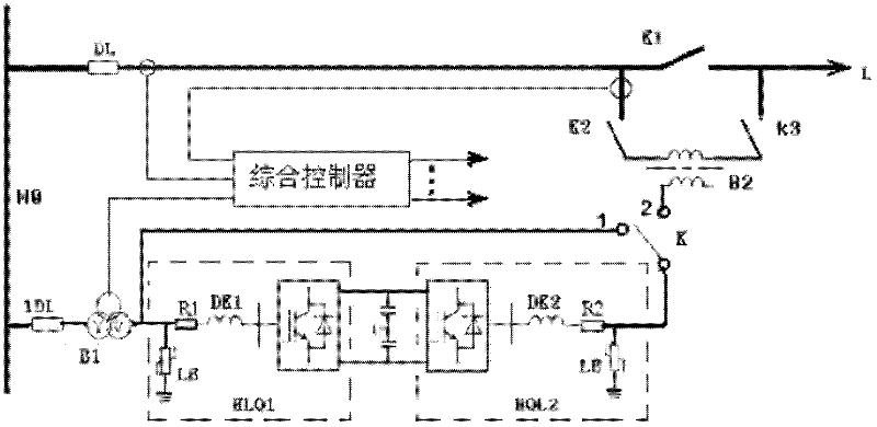
[0024] figure 1 Describes the principle wiring of the non-stop ice-melting and SVG reactive power static compensation composite device (hereinafter referred to as the composite device). The DC side of the two sets of converters HLQ1 and HLQ2 share a set of DC capacitors. The AC side is electrically connected to the first converter transformer B1 on the bus M0 of the substation, and the AC side of the second group of converters HLQ2 is electrically connected to the transfer switch K. When K is at position 1, the two sets of converters operate in parallel on the low-voltage side of the first converter transformer B1. At this time, the integrated controller controls the two sets of converters according to the sinusoidal pulse width modulation technique (SPWM) in the prior art. At the same time, it runs in the working state of SVG reactive power static compensation (SVG reactive power static compensation technology is an existing technology, so it will not be described in detail)....


PUM


Abstract

The invention discloses a power-uninterrupted ice melting and SVG-type reactive static compensation compound device and a use method thereof. The device at least comprises two sets of converters, wherein the DC (direct current) sides of the two sets of converters share a set of DC capacitors to form a back-to-back conversion system, the AC (alternating current) side of the first set of converters is connected with the low-voltage side of a first converter transformer, the AC side of the second set of converters can be respectively connected with the low-voltage side of the first converter transformer or a second converter transformer through a switch disconnecting link, the high-voltage side of the first converter transformer is connected parallel to an alternating current bus of a transformer station, the high-voltage side of the second converter transformer is connected to a line to be subjected to ice melting in series through the switch disconnecting link, and the compound device is controlled by a comprehensive controller to operate. The use method of the compound device comprises a power-uninterrupted ice melting operating state and a reactive static compensation operating state, and the stability of a system can not be destroyed.

Description

technical field [0001] The invention relates to a power device, in particular to a composite device which can be used for non-stop deicing of power lines and SVG reactive power static compensation for power grids and its application method. Background technique [0002] The problem of icing on power lines occurs to varying degrees in some provinces and regions in southern my country every year. In particular, the rare ice disaster in 2008 brought serious disasters to the power grids of southern provinces. Long-term and large-scale power outages have great impact on the national economy and People's lives are greatly affected. Power grid icing is also an important issue of common concern to all countries in the world. [0003] Retrieve the ice-melting technology of international and domestic power lines, commonly used are divided into two categories: one is when a large area of ​​icing occurs and the line is out of service, manual or mechanical de-icing is used, the de-icing ...

Claims


Application Information

Patent Timeline
Patent Type & Authority Applications(China)
IPC IPC(8): H02G7/16H02J3/18
CPCH02G7/16H02J3/18Y02E40/12H02J3/1821Y02E40/10
Inventor 贺长宏贺瀚青
Owner 贺长宏
Features
  • Generate Ideas
  • Intellectual Property
  • Life Sciences
  • Materials
  • Tech Scout
  • Unparalleled Data Quality
  • Higher Quality Content
  • 60% Fewer Hallucinations
Learn More