Slag granulating and waste heat recovery device

A waste heat recovery device and slag granulation technology, which are applied in recycling technology, steam generation method using heat carrier, improvement of process efficiency, etc., can solve problems such as waste of secondary energy, environmental pollution, occupation of water resources, etc.

Inactive Publication Date: 2012-04-25
CENT IRON & STEEL RES INST
View PDF8 Cites 29 Cited by
  • Summary
  • Abstract
  • Description
  • Claims
  • Application Information

AI Technical Summary

Problems solved by technology

The main problems caused by the water flushing slag method are: (1) A large amount of water resources are occupied and fresh water is consumed. The water consumption for flushing slag per ton of liquid blast furnace slag is about 10 tons, and the fresh water consumption is about 1 ton
(2) The secondary energy is wasted. The physical heat of each ton of high-temperature liquid blast furnace slag is equivalent to about 60kg of standard coal, which is completely dissipated during the slag flushing process
[0003] To sum up, the water quenching treatment technology and the utilization method of metallurgical slag commonly used at present not only waste a lot of new water resources, but also cause very serious pollution to the environment, and also reduce the use of energy and resources efficiency
This method is far from being able to adapt to the development model of new industrialization and circular economy, and must be fundamentally changed and discarded

Method used


Image

  • Slag granulating and waste heat recovery device
  • Slag granulating and waste heat recovery device
  • Slag granulating and waste heat recovery device

Examples


Embodiment Construction

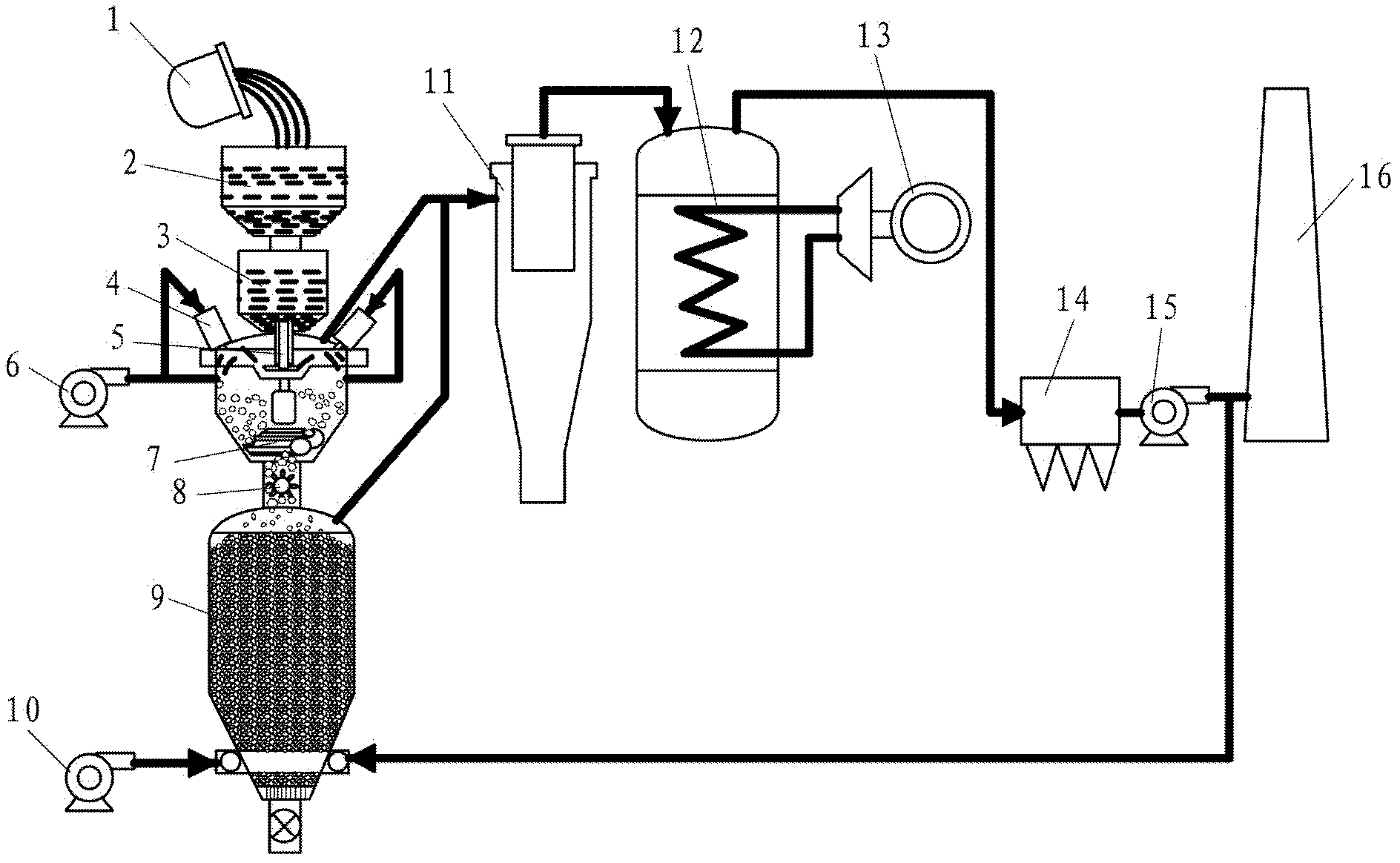
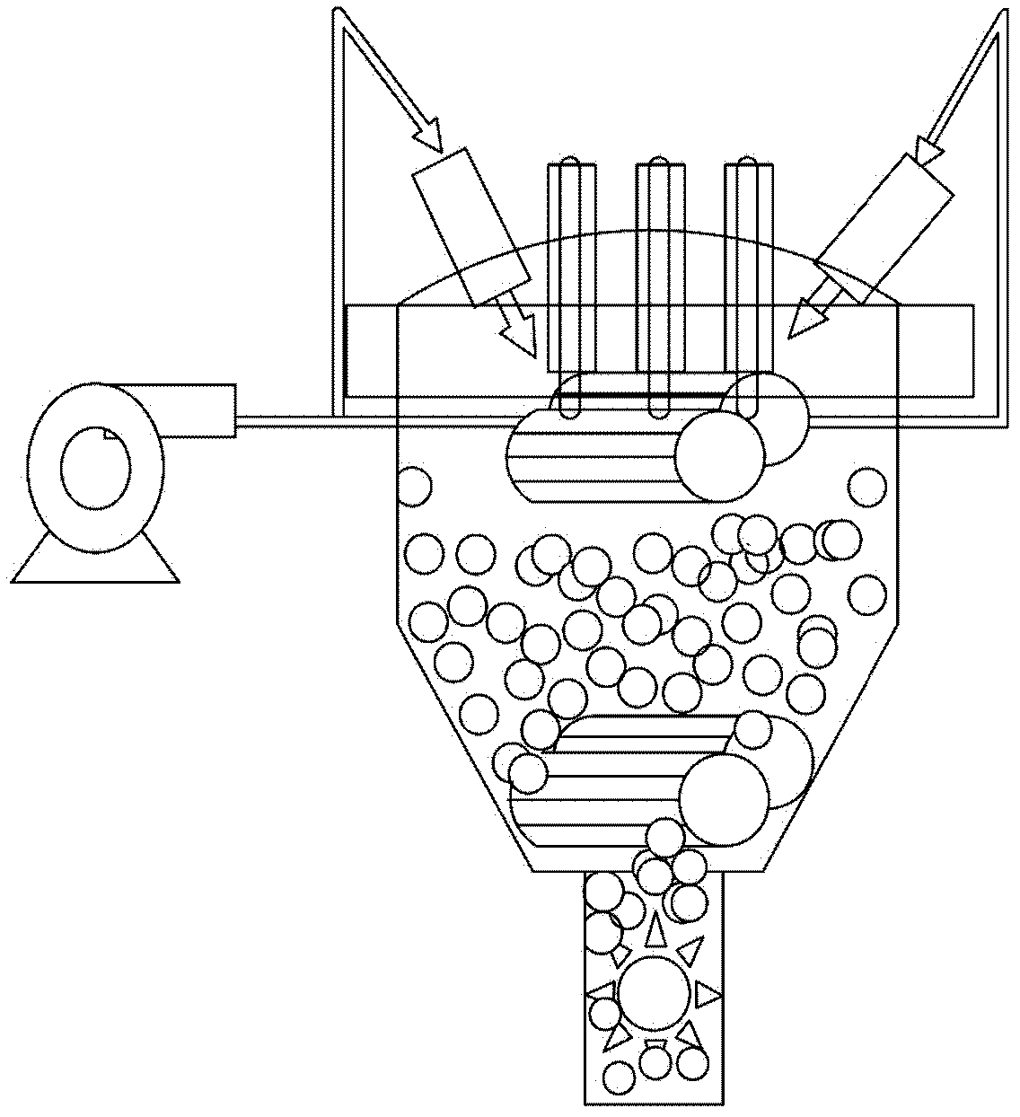
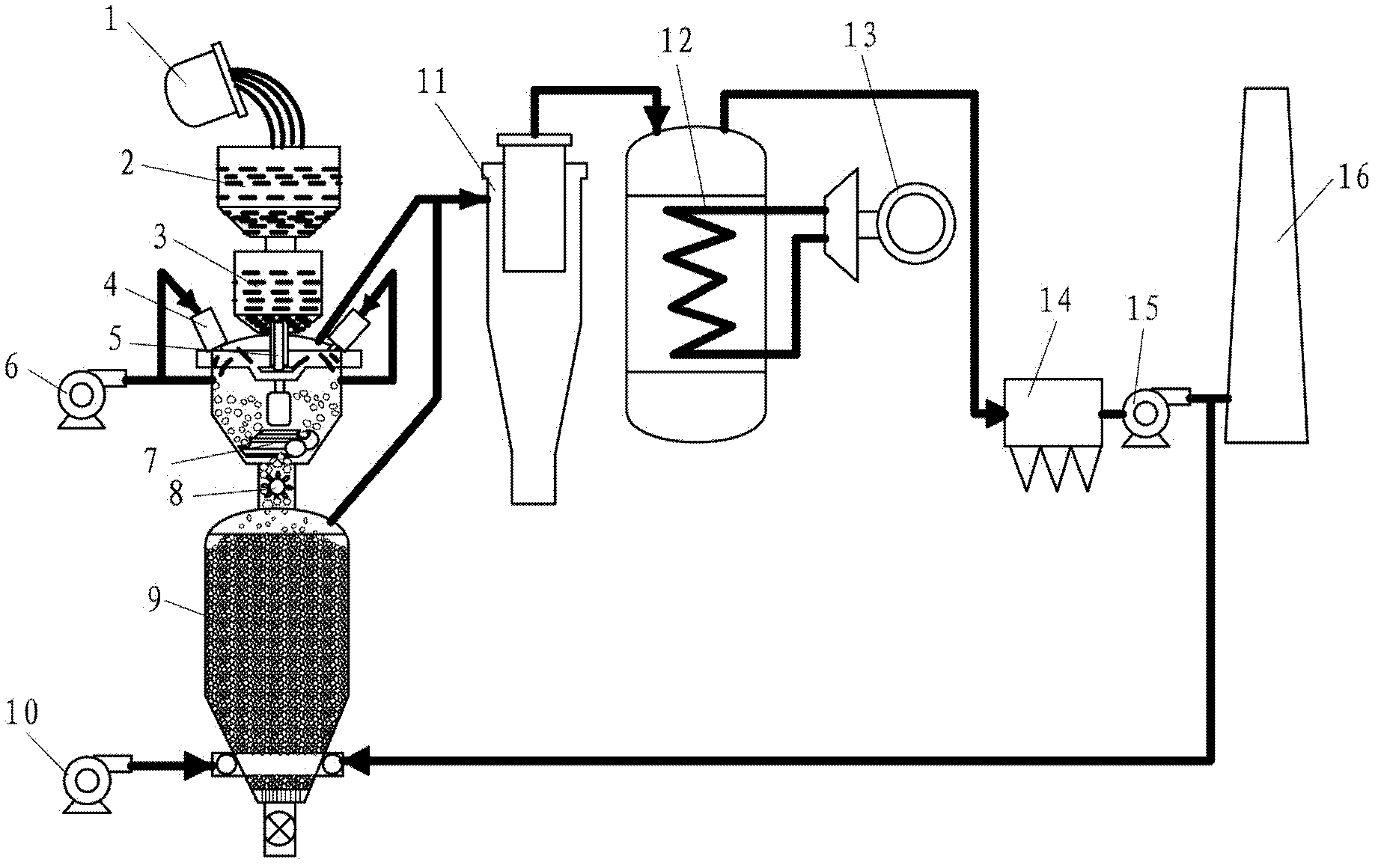
[0027] refer to figure 1 with figure 2 , the slag granulation and waste heat recovery device according to the present invention includes: slag tank 1, slag bag 2, nozzle 4, primary cooling fan 6, granulation device 7, discharge device 8, heat exchange shaft furnace 9, secondary cooling Fan 10, cyclone dust collector 11, waste heat boiler 12, dust collector 14, chimney 16.

[0028] The slag tank 1 accommodates the slag produced in the iron and steel smelting process, and the slag tank 1 can be transported to the slag processing site by a slag tank truck. The molten slag contained in the slag pot 1 can be poured into the slag ladle 2 by a crane. The main material inside the slag tank is refractory bricks, the diameter of the slag tank is 0.5-1.5m, and the height is 1-2m.

[0029] A nozzle (not shown) is provided at the lower part of the slag bag 2 to control the slag liquid to flow into the granulation device 7 for granulation treatment, wherein the nozzle may be a sliding n...


PUM

PropertyMeasurementUnit
diameteraaaaaaaaaa
diameteraaaaaaaaaa

Abstract

The invention provides a slag granulating and waste heat recovery device, comprising a slag pot, a slag ladle, a granulating device, a primary cooling fan, a discharge device, a secondary cooling fan, a heat exchange shaft furnace, a cyclone dust collector, a waste heat boiler, a dust collector and a chimney, wherein the slag pot is used for containing slag; a water port is arranged at the lower part of the slag ladle; the granulating device is used for granulating the slag in the slag ladle; the primary cooling fan is used for providing primary cooling air; the discharge device is used for discharging granulated slag; the secondary cooling fan is used for providing secondary cooling air; the heat exchange shaft furnace is used for performing heat exchange between the granulated slag discharged by the discharge device and the secondary cooling air; the cyclone dust collector is used for removing fine particle slag from the primary cooling air and the secondary cooling air; the waste heat boiler is used for generating high-temperature stream; the dust collector is used for collecting dust in the tail gas generated by the waste heat boiler; and the chimney is used for discharging the tail gas after dust collection. By using the slag granulating and waste heat recovery device according to the invention, no new water is consumed in the slag granulating process, the slag waste heatcan be effectively recovered for power generation, and the slag vitreous body after treatment can be used as a construction raw material.

Description

technical field [0001] The invention relates to a slag granulation and waste heat recovery device, in particular to a slag dry granulation and waste heat recovery device. Background technique [0002] Metallurgical slag is a by-product of the iron and steel production process, mainly from the ironmaking and steelmaking processes. The blast furnace slag produced per ton of pig iron is 300-400kg, and the converter slag produced per ton of steel is 80-120kg. At present, the processing method of blast furnace slag at home and abroad mainly adopts the method of water quenching, that is, the high-temperature liquid blast furnace slag is washed into solid particles with high-pressure water. The main problems caused by the water flushing slag method are: (1) A large amount of water resources are occupied and new water is consumed. The water consumption for flushing slag per ton of liquid blast furnace slag is about 10 tons, and the fresh water consumption is about 1 ton. (2) The s...

Claims


Application Information

Patent Timeline
Patent Type & Authority Applications(China)
IPC IPC(8): C21B3/06F22B1/18
CPCY02P10/20Y02W30/50
Inventor 齐渊洪周和敏王海风严定鎏
Owner CENT IRON & STEEL RES INST
Why Eureka
Try Eureka