Solution phase inversion membrane preparation solvent replacement and digestion device

A technology of solution phase inversion and membrane solvent, applied in chemical instruments and methods, membrane technology, semi-permeable membrane separation, etc., can solve the problems of large solvent residue, low solvent recovery rate, solvent loss, etc., to reduce investment and operation Cost, avoiding environmental pollution, and improving the effect of recovery rate

Inactive Publication Date: 2012-05-02
武钢集团有限公司 +1
View PDF5 Cites 4 Cited by
  • Summary
  • Abstract
  • Description
  • Claims
  • Application Information

AI Technical Summary

Problems solved by technology

[0003] The above-mentioned solvent displacement dissolution process has the following problems: (1) The cost of solvent recovery is high: since the coagulation baths are not connected to each other, and the direction of the film in the coagulation bath is from front to back, the solvent contained in the solution in different coagulation baths The concentration is different. The solution contains the highest concentration of solvent in the first coagulation bath that contacts the membrane at the front, and the concentration is lower as it goes further back.
Considering the cost and efficiency of solvent recovery, usually only the solvent in the effluent of the first 1 to 2 coagulation baths is recovered, and the solution with low solvent content discharged from other coagulation baths is discharged as wastewater and enters the sewage treatment system. On the one hand, it leads to waste of water resources, and the solvent in the water will also bring environmental impact; on the other hand, it is necessary to build a sewage treatment system, which increases the investment and operating costs of membrane production, and the loss of some solvents will also lead to a further increase in operating costs
(2) The residual amount of solvent in the film is large, and the solvent recovery rate is low: as the production continues, due to the gradual increase of the solvent concentration in the solution in each coagulation bath, the driving force for the dissolution of the solvent from the film in the same coagulation bath gradually increases. Decrease, the amount of residual solvent in the film gradually increases, and reaches the maximum when the coagulation bath solution needs to be replaced, resulting in an unstable dissolution rate of the solvent from the film, and a large amount of residual solvent in the film
(3) The continuous production of solvent replacement and dissolution cannot be realized: when the concentration of the solution in the coagulation bath reaches a predetermined value, it must be discharged regularly (or recovered or discharged as waste water) and re-injected for production. During the replacement of the solution, the membrane production facility must be stopped. transport, affecting the continuity of production

Method used


Image

  • Solution phase inversion membrane preparation solvent replacement and digestion device
  • Solution phase inversion membrane preparation solvent replacement and digestion device
  • Solution phase inversion membrane preparation solvent replacement and digestion device

Examples


Embodiment 1

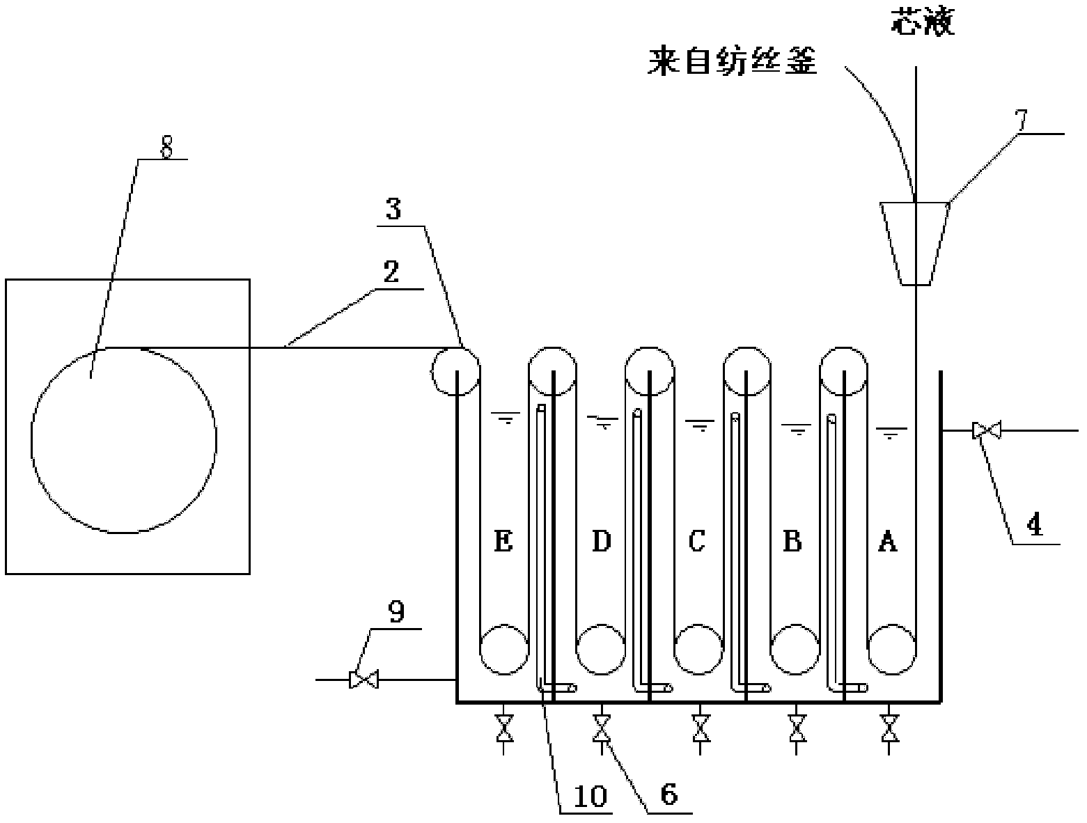
[0031] Device structure: see figure 2, the coagulation baths A, B, C, D, E are arranged in sequence from front to back, a tank wall 11 is shared between the two coagulation baths, the lower section of the coagulation bath E is provided with an injection port 9, and the upper section of the coagulation bath A is provided with an outlet 4, so The above-mentioned adjacent coagulation baths are all communicated via pipeline 10 (water pumps may or may not be installed on the pipeline 10), the upper end of the pipeline 10 is located at the upper section in the next adjacent coagulation bath, and the lower end of the pipeline 10 is located at the adjacent The lower section of the previous coagulation bath. The heights of the upper ends of the pipelines in the plurality of coagulation baths decrease successively from back to front (or equal height), and the bottom of each coagulation bath is also equipped with a discharge valve 6 for emptying the liquid in the tank when the system is...

Embodiment 2

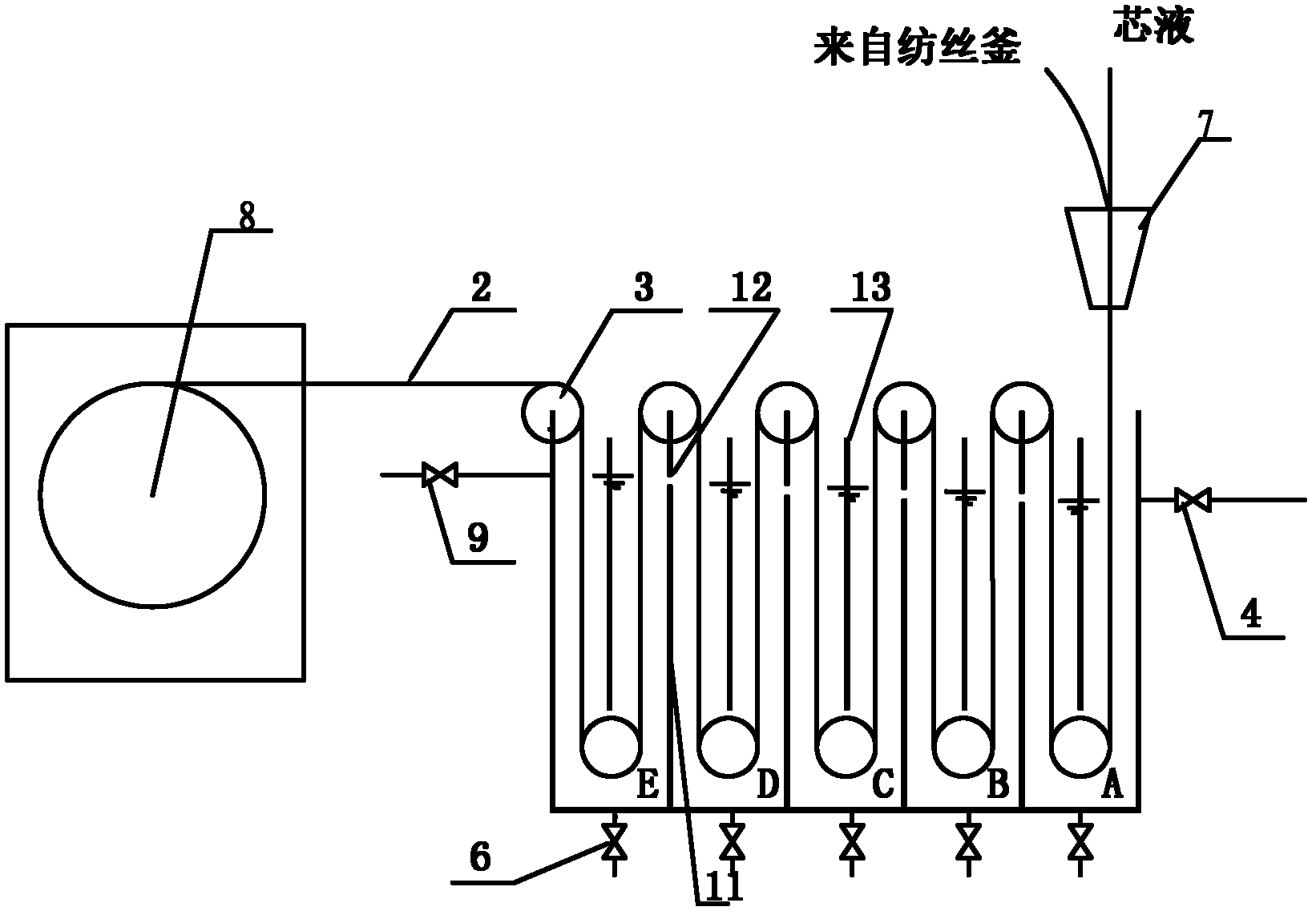
[0035] Device: see image 3 , different from Embodiment 1, the pipeline 10 is canceled, and the flow holes 12 on the tank wall 11 are communicated between adjacent coagulation baths, and the flow holes 12 are all positioned at the upper section of the tank wall 11 (the height of the flow holes 12 The overflow liquid level set for the tank), the center of the coagulation bath is vertically provided with a partition 13 along the axial direction of the pulley 3, and each coagulation bath is divided into two parts, and the lower end of the partition 13 is 20 ~ 50mm, the upper end of the separator 13 is 20-50mm higher than the liquid surface, and the lower end has a gap from the bottom of the tank for the membrane 2 and the liquid to pass through. The injection port 9 is located in the upper section of the coagulation bath E (preferably not lower than the liquid level). The height of the flow hole 12 on the tank wall 11 decreases successively from back to front (or is at a position...

Embodiment 3

[0039] Device: see Figure 4 , and embodiment 2 is different in that the partition 13 is canceled, the injection port 9 is located in the lower section of the coagulation bath E, and the positions of the flow holes 12 on the walls 11 of the coagulation bath are staggered up and down. In this embodiment, the coagulation bath E The flow hole 12 of coagulation bath D is in the upper section of the tank wall (its height is the overflow height set by coagulation bath E), and the flow hole 12 of coagulation bath D and coagulation bath C is in the lower section of the tank wall (close to the bottom of the tank) , in such a staggered arrangement (this embodiment is only an example, not limited to this arrangement). All the other are with embodiment 2.

[0040] crafting process:

[0041] After the fresh water enters the coagulation bath E, the liquid level of the coagulation bath E rises, and overflows from the flow hole in the upper section of the tank wall to the coagulation bath D...


PUM


Abstract

The invention relates to a solution phase inversion membrane preparation solvent replacement and digestion device and solves problems of present devices, such as high recovery cost, large solvent residual quantity in the membrane, low recovery rate of the solvent and difficulty in realizing solvent replacement and digestion continuous production. The technical scheme is as follows: the device provided by the invention contains a plurality of coagulation baths which are sequentially arranged from front to back; the first coagulation bath is provided with an outlet; the last coagulation bath is provided with an inlet; and adjacent coagulation baths communicate with each other through pipelines or openings on bath walls. The device provided by the invention has advantages of simple structure, high recovery rate of the solvent, low recovery cost and no sewage discharge, and can be used to realize continuous operation of the system.

Description

technical field [0001] The invention relates to a device used in the film-making process in water treatment, in particular to a solution phase inversion method film-making solvent replacement stripping device. Background technique [0002] The phase inversion method is to prepare a homogeneous polymer solution of a certain composition, and through a certain physical method to make the solution perform mass transfer and exchange of solvent and non-solvent in the surrounding environment, change the thermodynamic state of the solution, and make it change from homogeneous polymerization The solution undergoes phase separation, transforms into a three-dimensional macromolecular network gel structure, and finally solidifies to form a film. According to the different physical methods of changing the thermodynamic state of the solution, the phase inversion membrane method can be divided into the following types: solvent evaporation phase inversion method, heat induced phase inversio...

Claims


Application Information

Patent Timeline
Patent Type & Authority Applications(China)
IPC IPC(8): B01D67/00B01D71/06
Inventor 吴高明吴桂萍王增玉吴高宏
Owner 武钢集团有限公司
Why Eureka
Try Eureka