Switched reluctance motor bootstrapping driving circuit with low cost and high isolation characteristic

A technology of switched reluctance motor and drive circuit, which is applied in the direction of AC motor control, electrical components, electronic commutator, etc. It can solve the problems of low-voltage control signal waveform distortion, low-voltage control signal reversal, and influence, and achieve low cost Effect

Inactive Publication Date: 2012-05-02
SOUTHEAST UNIV
View PDF3 Cites 16 Cited by
  • Summary
  • Abstract
  • Description
  • Claims
  • Application Information

AI Technical Summary

Problems solved by technology

The isolation characteristics of the first two technical solutions are poor. The reason is that there is a parasitic Miller capacitance between the base-collector inside the triode or between the gate-source inside the MOS transistor used in the core switching circuit. As a result, the high-voltage drive signal in the drive circuit may be coupled to the low-voltage control signal channel of the microprocessor through the parasitic Miller capacitance, which may cause the low-voltage control signal waveform to be distorted, or cause the low-voltage control signal to reverse, resulting in the drive circuit. In addition, the consequences of poor isolation characteristics will also affect the dynamic characteristics of the drive circuit and power converter under the high-frequency pulse width modulation (PWM) control mode, that is, the drive The turn-on and turn-off time of the circuit and power converter cannot be consistent with the low-voltage control signal, and the expected control effect cannot be achieved
In the third scheme, a dedicated integrated driver chip is used. The chip is designed with a better isolation circuit, so its isolation characteristics and dynamic characteristics are better, but the cost is very high.

Method used


Image

  • Switched reluctance motor bootstrapping driving circuit with low cost and high isolation characteristic
  • Switched reluctance motor bootstrapping driving circuit with low cost and high isolation characteristic
  • Switched reluctance motor bootstrapping driving circuit with low cost and high isolation characteristic

Examples


Embodiment Construction

[0023] Below in conjunction with accompanying drawing and specific embodiment, further illustrate the present invention, should be understood that these embodiments are only for illustrating the present invention and are not intended to limit the scope of the present invention, after having read the present invention, those skilled in the art will understand various aspects of the present invention Modifications in equivalent forms all fall within the scope defined by the appended claims of this application.

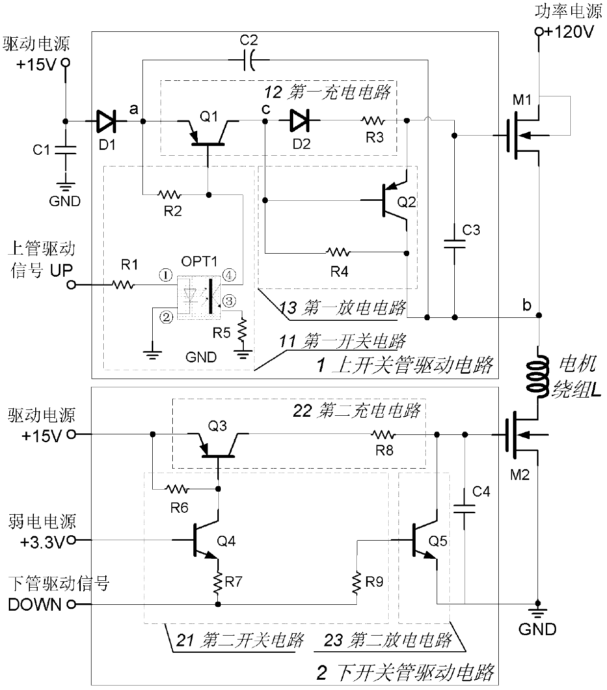
[0024] figure 1 The bootstrap drive circuit diagram for a low-cost, high-isolation switched reluctance motor:

[0025](1) It includes an upper switch tube drive circuit and a lower switch tube drive circuit. The input signal of the upper switch tube drive circuit includes the drive power supply, the upper tube drive signal UP from the microprocessor, the output terminal is connected to and drives the gate of the upper switch tube M1, the drain of the upper switch tube M...


PUM


Abstract

The invention discloses a switched reluctance motor bootstrapping driving circuit with low cost and high isolation characteristic with low cost and high isolation characteristic. The switched reluctance motor bootstrapping driving circuit comprises an upper switching tube driving circuit and a lower switching tube driving circuit, wherein the upper switching tube driving circuit comprises an optical-coupler-based first switching circuit, a first charging circuit, a first discharging circuit, a bootstrap capacitor and a bootstrap diode; and the lower switching tube driving circuit comprises a second switching circuit, a second charging circuit and a second discharging circuit. In the switched reluctance motor bootstrapping driving circuit disclosed by the invention, a single-power-supply operating mode based on the bootstrap capacitor is adopted, and a switching element taking a photoelectric coupler as a core switching circuit is adopted, influence of a high voltage driving signal to a low voltage control signal is avoided, safety of circuit control is improved; besides, conducting and closing times of the driving circuit and a power inverter are strictly consistent with a low voltage control signal of a micro processor, thus the switched reluctance motor bootstrapping driving circuit disclosed by the invention is applicable to a workplace under high frequency PWM (Pulse Width Modulation) control mode.

Description

technical field [0001] The invention relates to a switched reluctance motor, in particular to a drive circuit of the switched reluctance motor. Background technique [0002] Switched reluctance motors have some unique advantages, such as simple structure, firmness, maintenance-free, large torque and low current at start-up and low speed; wide range of high-speed constant power range, good performance, and excellent performance in a wide range of speed and power. High output and high efficiency; it can operate with phase loss and has strong fault tolerance; it can be flexibly controlled and can easily realize four-quadrant operation; it has strong regenerative braking ability, etc. This makes the switched reluctance motor system widely used in household appliances, general industry, servo and speed control systems, traction motors, high-speed motors, aerospace and other fields. A switched reluctance motor is an electromechanical energy conversion device. According to the re...

Claims


Application Information

Patent Timeline
Patent Type & Authority Applications(China)
IPC IPC(8): H02P6/14H02M1/08H02P25/08
Inventor 孙伟锋钟锐刘海龙陈磊刁龙陆生礼时龙兴
Owner SOUTHEAST UNIV
Why Eureka
Try Eureka