Stripping method of thin-film material

A thin film material and thin film technology, applied in the field of thin film material peeling, can solve the problems of high production cost, poor physical properties of the thin film, and reduced nonlinear optical coefficient of the lithium niobate thin film, so as to reduce the production cost and improve the quality of the thin film. Effect

Active Publication Date: 2012-05-09
JINAN JINGZHENG ELECTRONICS
View PDF3 Cites 22 Cited by
  • Summary
  • Abstract
  • Description
  • Claims
  • Application Information

AI Technical Summary

Problems solved by technology

Therefore, in Documents 1 and 2, the dose of ion implantation is relatively large (4×10 16 ions / cm 2 above) to ensure that there are enough ions to generate high-density bubbles, but the large-dose ion implantation has brought two disadvantages. One is that the implantation time is long, and the corresponding production cost is high. The second is the large-dose ion implantation. It will damage the crystal structure of the film and deteriorate the physical properties of the film
For example, in Document 4, a large dose of helium ion implantation caused the nonlinear optical coefficient of the lithium niobate thin film to be reduced to about half of that of the bulk material.

Method used


Image

  • Stripping method of thin-film material
  • Stripping method of thin-film material

Examples


Embodiment Construction

[0010] way 1

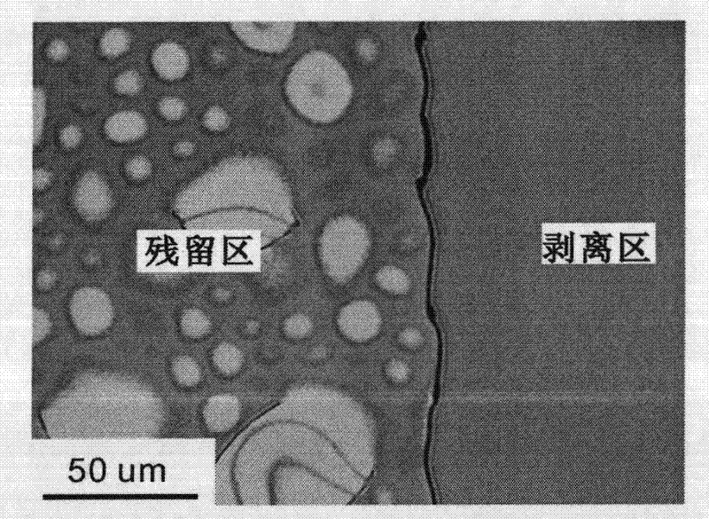
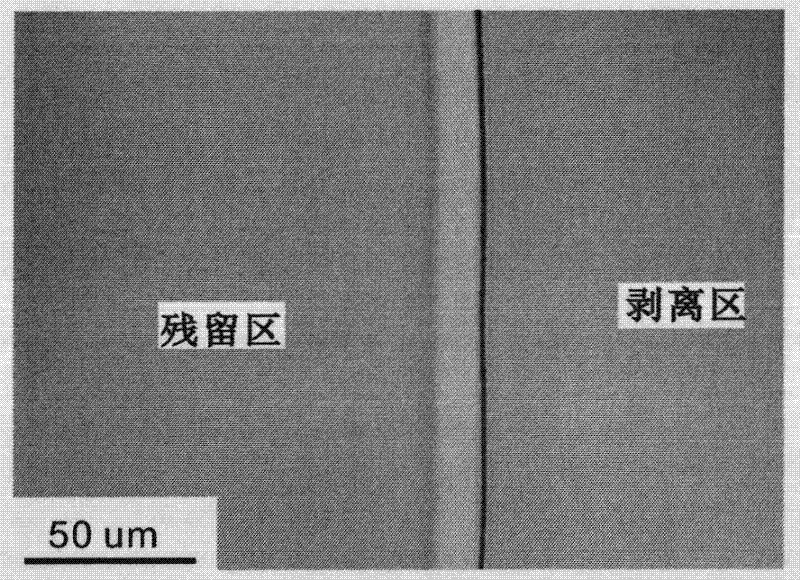
[0011] The lithium niobate (or lithium tantalate) wafer A is implanted with helium ions, and the implantation dose can be 1×10 16 ions / cm 2 to 4×10 16 ions / cm 2 In between, deposit a layer of silicon dioxide on the surface of another piece of lithium niobate crystal (or lithium tantalate) piece B and then polish it. After bonding A and B, raise the temperature to about 170°C and stay for 10 hours to make the wafer reach the best bonding strength, and then within 10 minutes, raise the temperature to 230°C. The internal stress caused by this temperature change makes the film Lithium niobate (or lithium tantalate) film is obtained after polishing.

[0012] way 2

[0013] The lithium niobate (or lithium tantalate) wafer A is implanted with helium ions, and the implantation dose can be 1×10 16 ions / cm 2 to 4×10 16 ions / cm 2 In between, deposit a layer of silicon dioxide on the surface of another lithium niobate (lithium tantalate) wafer B and then polish it....


PUM


Abstract

A technical process for manufacturing a monocrystal lithium niobate thin film or a monocrystal lithium tantalate thin-film material. After bonding of wafers, reduction of crystal lattice intensity of a damage layer caused by ion implantation and differences of thermal expansion coefficients between a silicon dioxide layer and a lithium niobate (lithium tantalate) crystal are utilized to select an appropriate heat treatment process and form stress in wafer set, so as to strip the film. The process can substantially reduce ion implantation dosage, thereby reducing production cost and increasing film quality.

Description

technical field [0001] The invention relates to a process for making single crystal lithium niobate thin film or single crystal lithium tantalate thin film material. Background technique [0002] Single crystal lithium niobate thin film or single crystal lithium tantalate thin film material with high refractive index difference has a very wide application prospect in integrated optics, optoelectronic components and nonlinear optics. Documents 1 and 2 respectively reported the methods of fabricating lithium niobate single crystal thin film and lithium tantalate single crystal thin film. The basic steps include ion implantation, silicon dioxide deposition and polishing, sample cleaning, direct bonding, heat treatment separation, thin film Polishing and other processes. The basic manufacturing principle can be explained by the process introduced in Document 3: (hydrogen or helium) ion implantation is performed on lithium niobate wafer or lithium tantalate wafer. After the ions...

Claims


Application Information

Patent Timeline
Patent Type & Authority Applications(China)
IPC IPC(8): C30B29/30C30B33/00C30B33/02
Inventor 胡文
Owner JINAN JINGZHENG ELECTRONICS
Why Eureka
Try Eureka