
High-precision electrical stimulation controller

A controller and electric stimulation technology, applied in the field of biomedical engineering, can solve the problems of heavy technical maintenance workload, low accuracy, prolonging charging time, etc., to achieve statistical data and experience accumulation, easy to carry, small size Effect

Inactive Publication Date: 2012-05-30
DALIAN CHUANGDA TECH TRADE MARKET
View PDF0 Cites 0 Cited by
  • Summary
  • Abstract
  • Description
  • Claims
  • Application Information

AI Technical Summary

Problems solved by technology

For example, the circuit of the timing control unit is completed through the RC charging and discharging circuit, but once the DC voltage drops, the charging time will be extended, so the time control of the electrical stimulation waveform is very inaccurate
In addition, the adjustment and parameter setting of the system are completed through dial switches and potentiometers, which reduces the flexibility of the system, and the accuracy is not high, quantitative control cannot be achieved, and the parameters used cannot be displayed, which makes clinical practice difficult. Statistics and research are difficult to conduct
Such an adjustment method is also quite difficult and inconvenient for non-professionals, such as patients and medical staff.
In addition, a large number of discrete components increase the possibility of system failure, and the workload of technical maintenance is also very large

Method used


Image

  • High-precision electrical stimulation controller
  • High-precision electrical stimulation controller
  • High-precision electrical stimulation controller

Examples


Embodiment Construction

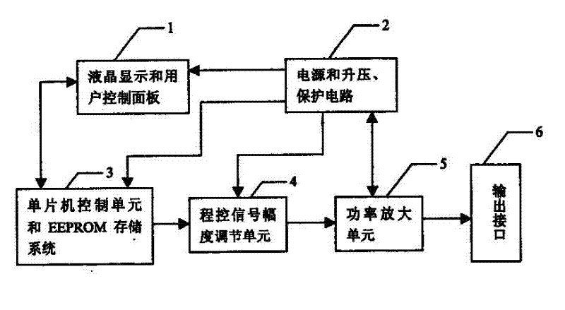
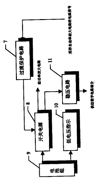
[0010] The controller of the present invention is composed of liquid crystal display and control panel 1, power supply and booster, protection circuit 2, single-chip microcomputer control unit and EEPROM storage system 3, program-controlled signal amplitude adjustment unit 4, power amplifier circuit 5 and output interface 6. The power supply and voltage boosting and protection circuit 2 are composed of an overcurrent protection circuit 7 , a switching power supply 8 , a battery pack 9 , a low voltage indicator 10 , and a voltage stabilizing circuit 11 .

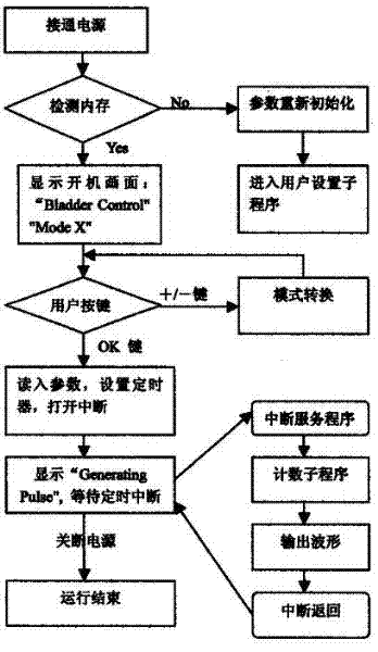
[0011] After the controller of the present invention is powered on, the controller first self-inspects the memory, re-initializes the parameters, and enters the user setting subroutine, the liquid crystal display and the control panel 1 display the boot screen, and the user presses the keys to switch modes, and loops to increase and decrease item by item Parameters, parameter testing, determine the preservation of parameters, ...


PUM


Abstract

The invention discloses a high-precision electrical stimulation controller relating to an in vitro control technology for functional electrical stimulation in the biomedical engineering field. The high-precision electrical stimulation controller is an intelligent electrical stimulation controller. The high-precision electrical stimulation controller comprises a liquid crystal display, a control panel, a power supply, a boosting protection circuit, a single chip microcomputer control unit, an EEPROM (Electrically Erasable Programmable Read-Only Memory) storage system, a program control signal amplitude regulating unit, a power amplification circuit and an output interface. Through an integral system comprising a single chip microcomputer and a peripheral electronic device, functional electrical stimulation waveforms with multiple modes are precisely generated, controlled and outputted, and an electrical stimulation signal with enough power is provided. The electrical stimulation signal provided by the controller can be connected to various stimulation electrodes for functional compensation or functional rehabilitation, a user can flexibly set and regulate the electrical stimulation signal by the control panel and a man-machine conversation process and various determined parameter number values can be displayed on the liquid crystal display. The high-precision electrical stimulation controller has the advantages of small size, convenience in carrying, reliable performance and safety.

Description

technical field [0001] The invention belongs to the field of biomedical engineering, and in particular relates to a high-precision electric stimulation controller. Background technique [0002] The techniques and devices for functional recovery or compensation through electrical stimulation have been reported at home and abroad, such as the British Finetech-Brindley Bladder Control Technology ("The Finetech-Brindley Bladder Controller: Notes for Surgeons and Physicians", March 1994 related part), in the seventies of the twentieth century, there were products of electric stimulation urination controllers on the market, but there were no patents and electric schematic diagrams. The control method and system of this product are closer to the US patent "Method and System for Controlling Bladder Evacuation" (Inventers: Tanagho, et al. , Patent No. 4607639, August 26, 1986). The patent uses discrete electronic components to form each unit of the system, using analog signals. Fo...

Claims


Application Information

Patent Timeline
Patent Type & Authority Applications(China)
IPC IPC(8): A61N1/36
Inventor 杜冲
Owner DALIAN CHUANGDA TECH TRADE MARKET
Learn More