
Method for treating contaminated soil by combining in-situ heat strengthening and soil vapor extraction technology

A polluted soil, thermal strengthening technology, applied in the restoration of polluted soil, etc., can solve secondary pollution and other problems

Inactive Publication Date: 2012-06-27
TIANJIN ECOLOGY CITY ENVIRONMENTAL PROTECTION +1
View PDF5 Cites 72 Cited by
  • Summary
  • Abstract
  • Description
  • Claims
  • Application Information

AI Technical Summary

Problems solved by technology

[0007] Aiming at the deficiencies in the above-mentioned problems, the present invention provides a method for treating polluted soil with in-situ thermal intensification combined with soil gas phase extraction technology, which can achieve volatile and semi-volatile effects on various types of soil and various surface conditions. In-situ rapid and low-cost remediation of soil polluted by sexual organic matter, and avoid secondary pollution caused by large-scale excavation of soil

Method used


Image

  • Method for treating contaminated soil by combining in-situ heat strengthening and soil vapor extraction technology
  • Method for treating contaminated soil by combining in-situ heat strengthening and soil vapor extraction technology
  • Method for treating contaminated soil by combining in-situ heat strengthening and soil vapor extraction technology

Examples


Embodiment Construction

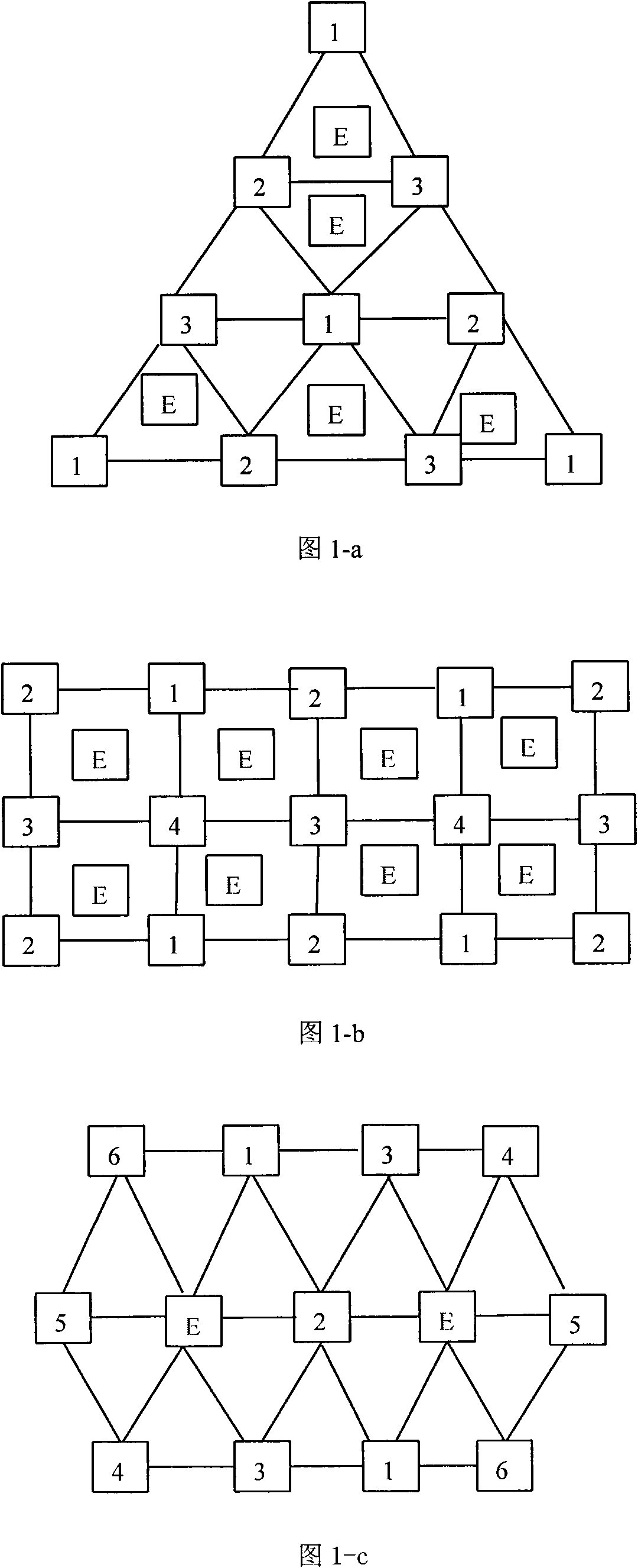
[0023]Figure 1 is a view showing the layout of different forms of heating wells. The heating wells are arranged in a certain form. The form of the layout is conducive to the heater to transfer heat to the adjacent polluted soil in a uniform manner in a long period of time, so as to reduce the removal of pollutants. Repair time required. Specifically, triangles, quadrilaterals, hexamorphs, polygons, etc. can be used, which should cover the entire contaminated area. The interval between heating wells is about 0.9-6 meters, which can be determined according to the specific area of ​​the contaminated area. Fig. 1-a to Fig. 1-c show that the heating wells are arranged in triangular, quadrilateral and hexagonal forms respectively.

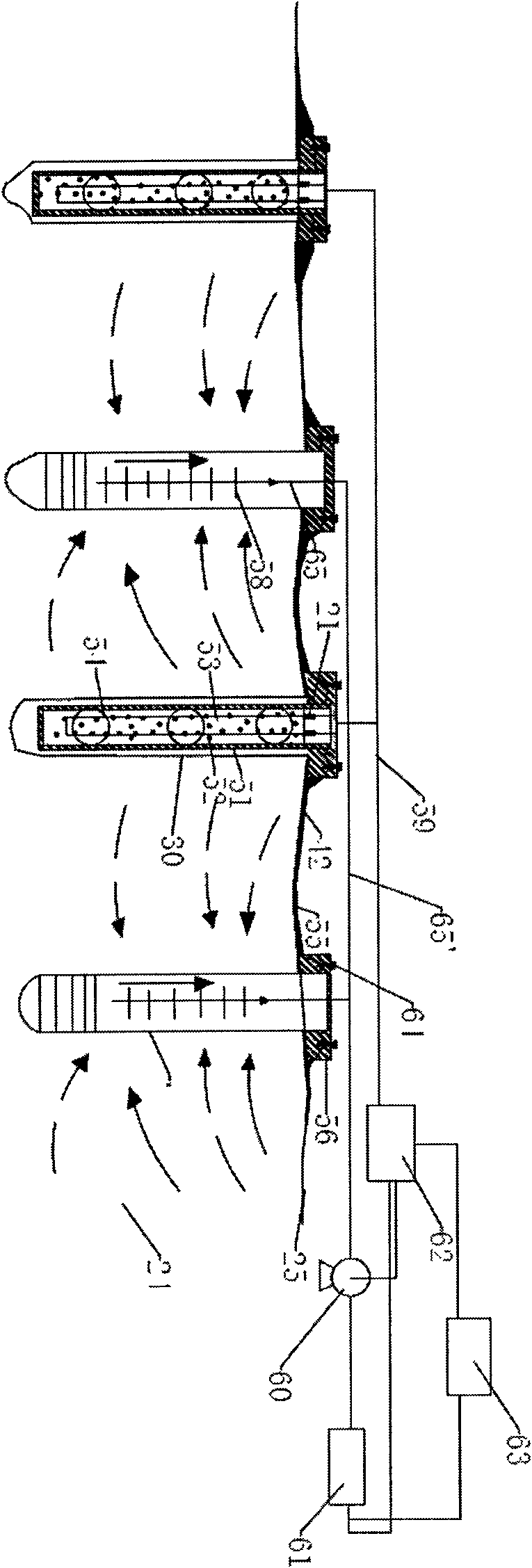
[0024] figure 2 It shows the layout of the heating well and the extraction well and the view of the embodiment of the external connection, in this embodiment, a quadrilateral layout is adopted. The heating wells are connected with each other by conduct...


PUM


Abstract

The invention discloses a method for treating contaminated soil by combining in-situ heat strengthening and a soil vapor extraction technology, which is characterized in that a heating well with a certain form is formed in a contaminated area, a heater part is provided in the heating well, and a sleeve pipe is installed, a catalyst is filled in the sleeve pipe for accelerating the high temperature decomposition of the pollutant into simple micromolecular substances. At least one well bore is drilled at the central contaminated area of the heating well which is arranged in the certain form to form an extraction well, a vacuum system is provided for realizing the extraction of the contaminated tail gas. the heating well provides heat to contaminated soil of the heating well and the adjacent areas through the thermal conductivity of the heater part arranged in the heating well, soil is heated, the soil pollutant is subjected to processes of evaporation, in-situ pyrolysis, oxidation, combustion, distillation and the like to form tail gas like simple micromolecular gas, water and pollutant steam, then the tail gas is extracted by the vacuum system in the extraction well, and is connected to a tail gas collection pipeline of the extraction well to send to the ground surface, the pollutant in tail gas is treated through a pollutant treatment facility which is installed on the ground surface. The method also comprises an impervious sealing plate which is arranged on the contaminated soil area ground surface for minimizing the gas exchange of the heating well, the extraction well and atmosphere, and preventing the pollutant from entering in atmosphere to form secondary pollution, and a thermal insulation layer is arranged above or below the impervious sealing plate for avoiding the dissipation of heat.

Description

technical field [0001] The invention belongs to the technical field of environmental protection, and in particular relates to soil remediation technology, especially a method for treating polluted soil with in-situ thermal strengthening combined with soil gas phase extraction technology. Background technique [0002] Since my country's reform and opening up, a large number of polluted industrial sites have been left behind due to the relocation of chemical enterprises, and environmental pollution accidents and human health damage incidents caused by the relocation of polluting enterprises have also occurred from time to time, which has become one of the main factors of environmental disputes caused by urban land development. one. Pollutants such as benzene and toluene emitted by chemical enterprises and organochlorine pesticides used in agriculture have gradually increased soil pollution. The development of the petroleum industry has brought gasoline, diesel and other volati...

Claims


Application Information

Patent Timeline
IPC IPC(8): B09C1/06
Inventor 张景辉刘朝辉李野杨伟王文茜王尧卢丹邵兆俊韩嵩西伟力王旭东毕涛
Owner TIANJIN ECOLOGY CITY ENVIRONMENTAL PROTECTION
Learn More