Solar energy hot water and boiler waste heat recovery integrated system

A technology of solar hot water and boiler waste heat, applied in solar thermal power generation, solar thermal devices, preheating, etc., can solve problems such as large restrictions, strong boiler dependence, and low water temperature

Inactive Publication Date: 2012-07-04
DALIAN DECHANG ENERGY ENVIRONMENT DEV
View PDF7 Cites 5 Cited by
  • Summary
  • Abstract
  • Description
  • Claims
  • Application Information

AI Technical Summary

Problems solved by technology

[0002] Although the solar water heating system has the advantages of economy, environmental protection, low-carbon emission reduction, etc., it is greatly affected and restricted by the season, especially in the northern regions with high latitudes, which is limited by factors such as solar radiation and sunshine time. The solar water heating system The following problems often occur: low water temperature, low heat collection efficiency, easy frost heaving and bursting of pipelines, need to be equipped with auxiliary heating devices, and increase costs
The boiler waste heat recovery device uses the high-temperature flue gas during boiler operation to exchange heat with the medium through the heat pipe to realize the functions of replenishing water to the boiler or providing domestic water to the outside world, which can improve the thermal efficiency of the boiler and reduce fuel consumption. However, this method The dependence on the boiler is extremely strong. Once the boiler stops running, the waste heat recovery device cannot be used; especially the boilers of heating companies do not operate in spring, summer and autumn in a year, and the waste heat of the boiler cannot be used provide heat
In summary, there are certain defects in the above two heating systems.

Method used


Image

  • Solar energy hot water and boiler waste heat recovery integrated system
  • Solar energy hot water and boiler waste heat recovery integrated system

Examples


Embodiment Construction

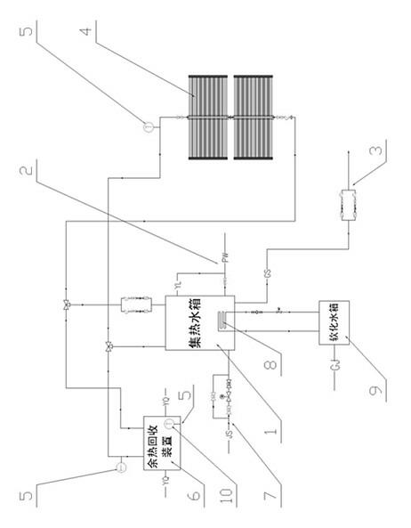
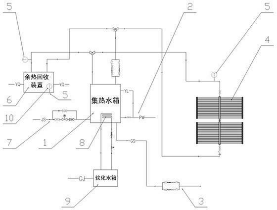
[0008] Specific embodiments of the present invention will be described below with reference to the accompanying drawings. like figure 1 Shown: an integrated system of solar hot water and boiler waste heat recovery, including a hot water collection tank 1, a sewage pipe 2 is arranged at the bottom of the hot water collection tank 1, and a water supply pipe 3 is also connected to the hot water collection tank 1 ; The water collecting tank 1 is connected with the solar collector 4 through a circulation pipeline, and a temperature detection device 5 is also provided in the return water pipeline of the solar collector 4; The recovery device 6 is connected, and the waste heat recovery device 6 is arranged at the exhaust gas discharge port of the boiler to exchange heat with the high-temperature flue gas there, and transport the heated water body to the hot water collection tank 1 for storage. The return water pipeline part of the waste heat recovery device 6 is also provided with a...


PUM


Abstract

The invention discloses a solar energy hot water and boiler waste heat recovery integrated system, which comprises a heat collecting water tank, wherein the heat collecting water tank is provided with a blowdown pipeline and a water supply pipeline. The solar energy hot water and boiler waste heat recovery integrated system is characterized in that the heat collecting water tank is communicated with a solar thermal collector through a circulating pipeline, a backwater pipeline of the solar thermal collector is further provided with a temperature detecting device, the heat collecting water tank is further communicated with a waste heat recovery device through the circulating pipeline, the waste heat recovery device is arranged on a waste gas discharge port of a boiler, a recovery pipeline of the waste heat recovery device is also provided with the temperature detecting device, and is communicated with a water inlet pipeline with the heat collecting water tank, a heat exchange coil is arranged in the heat collecting water tank, the heat exchange coil is communicated with a soft water tank, and the soft water tank is communicated with a boiler inner cavity through the circulating pipeline. The solar energy hot water and boiler waste heat recovery integrated system is simple in structure, ingenious in design and reasonable in layout, and creatively organically combines a solar heating device and a boiler waste heat device into an integrated system.

Description

technical field [0001] The invention relates to a heating system, in particular to an integrated system of solar hot water and boiler waste heat recovery. Background technique [0002] Although the solar water heating system has the advantages of economical environmental protection, low-carbon emission reduction, etc., it is greatly affected and restricted by the season, especially in the northern regions of high latitudes, and is limited by factors such as solar radiation amount and sunshine time. The following problems often occur: low water temperature, low heat collection efficiency, easy frost heaving and bursting of pipelines, the need for auxiliary heating devices, and increased costs. The boiler waste heat recovery device uses the high-temperature flue gas during the operation of the boiler to exchange heat with the medium through the heat pipe to realize the functions of replenishing water to the boiler or providing domestic water to the outside world, which can imp...

Claims


Application Information

Patent Timeline
Patent Type & Authority Applications(China)
IPC IPC(8): F24J2/00F24J2/04F24J2/40F22D1/16
CPCY02E10/44
Inventor 梁振杰郭健王志伟薛丹宋玲玲吴戈军
Owner DALIAN DECHANG ENERGY ENVIRONMENT DEV
Why Eureka
Try Eureka