High-accuracy fluorescence anisotropy microscopic imaging device and method

An anisotropic, microscopic imaging technology, used in fluorescence/phosphorescence, material excitation analysis, etc., can solve the problems of difficult position identification of fluorescent spheres, insufficient observation, obvious noise, etc.

Inactive Publication Date: 2012-07-04
GUANGDONG UNIV OF TECH
View PDF5 Cites 20 Cited by
  • Summary
  • Abstract
  • Description
  • Claims
  • Application Information

AI Technical Summary

Problems solved by technology

However, as described in "Imaging lifetime and anisotropy spectrum in the frequency domain," in Journal of Microscopy-Oxford. vol. 234, 2009, pp. 80-88, the traditional fluorescence polarization microscopy imaging method is used Observations on different samples show that the light intensity spectrum distribution of rhodamine 6G and 59% glycerol solution is uniform, but in the fluorescence anisotropy diagram of fluorescence polarization, noise can be clearly seen
And for observing the one-dimensional spatial distribution light intensity spectrum of rhodamine 6G and 50% glycerol solution and 670nm fluorescent sphere, the corresponding spectral line positions can be clearly distinguished from the light intensity spectrum, but in the anisotropy spectrum, the noise Extremely obvious, it is difficult to identify the position of the fluorescent ball
In "Wide-field time-resolved fluorescence anisotropy imaging (TR-FAIM): Imaging the rotational mobility of a fluorophore," in Review of Scientific Instruments. vol. 74, 2003, pp. 182-192 As mentioned in , for CHO cells expressing erbB1–eGFP fluorescence image and anisotropy image spectrum, the internal details of the cell can be resolved on the light intensity image, but the interior details of the cell can hardly be resolved on the anisotropy image of the fluorescence polarization details, indicating that the resolution of existing fluorescence anisotropy microscopy imaging methods is not enough to support finer observation of cells

Method used


Image

  • High-accuracy fluorescence anisotropy microscopic imaging device and method
  • High-accuracy fluorescence anisotropy microscopic imaging device and method
  • High-accuracy fluorescence anisotropy microscopic imaging device and method

Examples


Embodiment Construction

[0043] The present invention is described in detail below in conjunction with accompanying drawing and embodiment:

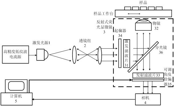
[0044] The structure of the high-precision fluorescence anisotropy microscopic imaging device proposed by the present invention is as follows: figure 2 As shown, the device sequentially includes an excitation light source 1, a lens group 2, a reflective fluorescence microscope 3, a camera 4, and a computer 5. In the embodiment, the camera 4 is a CCD camera, and the lens group 2 is composed of two lenses. The core part is the reflective fluorescence microscope. The light source can be high brightness LED, mercury lamp or xenon lamp. The Lambertian distribution illumination light intensity emitted by the excitation light source 1 is converted into a Gaussian light intensity distribution by the lens group 2 , and connected to the reflective fluorescence microscope 3 . The light source with Gaussian light intensity distribution passes through the polarizer 34, th...


PUM


Abstract

The invention relates to a high-accuracy fluorescence anisotropy microscopic imaging device and method. The imaging method comprises the following steps of: on a reflective fluorescence microscope, leading lights emitted by a light source to pass through a polarizer, an excitation filter plate and a spectroscope, and then focusing the lights on a sample; leading fluorescence reflected by the sample to pass through an objective lens, the spectroscope and an emission filter plate, and then imaging on an image plane of a CCD (Charge-Coupled Device) camera through an adjustable angle analyzer; controlling the adjustable angle analyzer to rotate around an optical axis of an imaging optical path step by step by using a computer, wherein when the adjustable angle analyzer rotates by an angle every time, the CCD camera shoots a frame of polarized fluorescence image, M images are totally shot; and finally calculating fluorescence anisotropic images from the M images by using Fourier transform.The imaging method is characterized in that the measuring resolution ratio of the fluorescence anisotropy is greatly improved by establishing a single-channel fluorescence analyzing optical path; andthe microscopic imaging system has higher stability and better anti-jamming capability.

Description

technical field [0001] The invention relates to a method and an instrument for fluorescent microscopic imaging, in particular to a device and a method for performing high-precision fluorescent anisotropic microscopic imaging on biological samples by means of a reflective wide-field fluorescent microscope. Background technique [0002] Optical microscopy imaging technology can observe living cells in the normal state of the sample, keeping the real environment of the sample to the greatest extent. However, due to the limitations of Abbe's principle, it is impossible to use conventional wide-field microscopy imaging techniques to study the interaction between molecules at the nanometer scale. Fluorescence anisotropic microscopic imaging technology is based on the optical phenomenon of fluorescence polarization. It can perform functional imaging of the interaction between fluorescent molecules at the nanometer scale. It has strong signal selectivity. Compared with other functio...

Claims


Application Information

Patent Timeline
Patent Type & Authority Applications(China)
IPC IPC(8): G01N21/64
Inventor 周延周陈辞白玉磊王钦若
Owner GUANGDONG UNIV OF TECH
Why Eureka
Try Eureka