Method for preparing BiFeO3 ferroelectric thin film photovoltaic battery on glass substrate

A ferroelectric thin film and glass substrate technology, which is applied in the manufacture of circuits, electrical components, and final products, to achieve the effects of wide sources, superior photovoltaic performance, and uniform grain size

Inactive Publication Date: 2012-07-04
SHANGHAI JIAO TONG UNIV
View PDF3 Cites 18 Cited by
  • Summary
  • Abstract
  • Description
  • Claims
  • Application Information

AI Technical Summary

Problems solved by technology

[0006] So far, there is no method for preparing BFO ferroelectric thin films and their photovoltaic cells on glass substrates

Method used


Image

  • Method for preparing BiFeO3 ferroelectric thin film photovoltaic battery on glass substrate
  • Method for preparing BiFeO3 ferroelectric thin film photovoltaic battery on glass substrate
  • Method for preparing BiFeO3 ferroelectric thin film photovoltaic battery on glass substrate

Examples


Embodiment 1

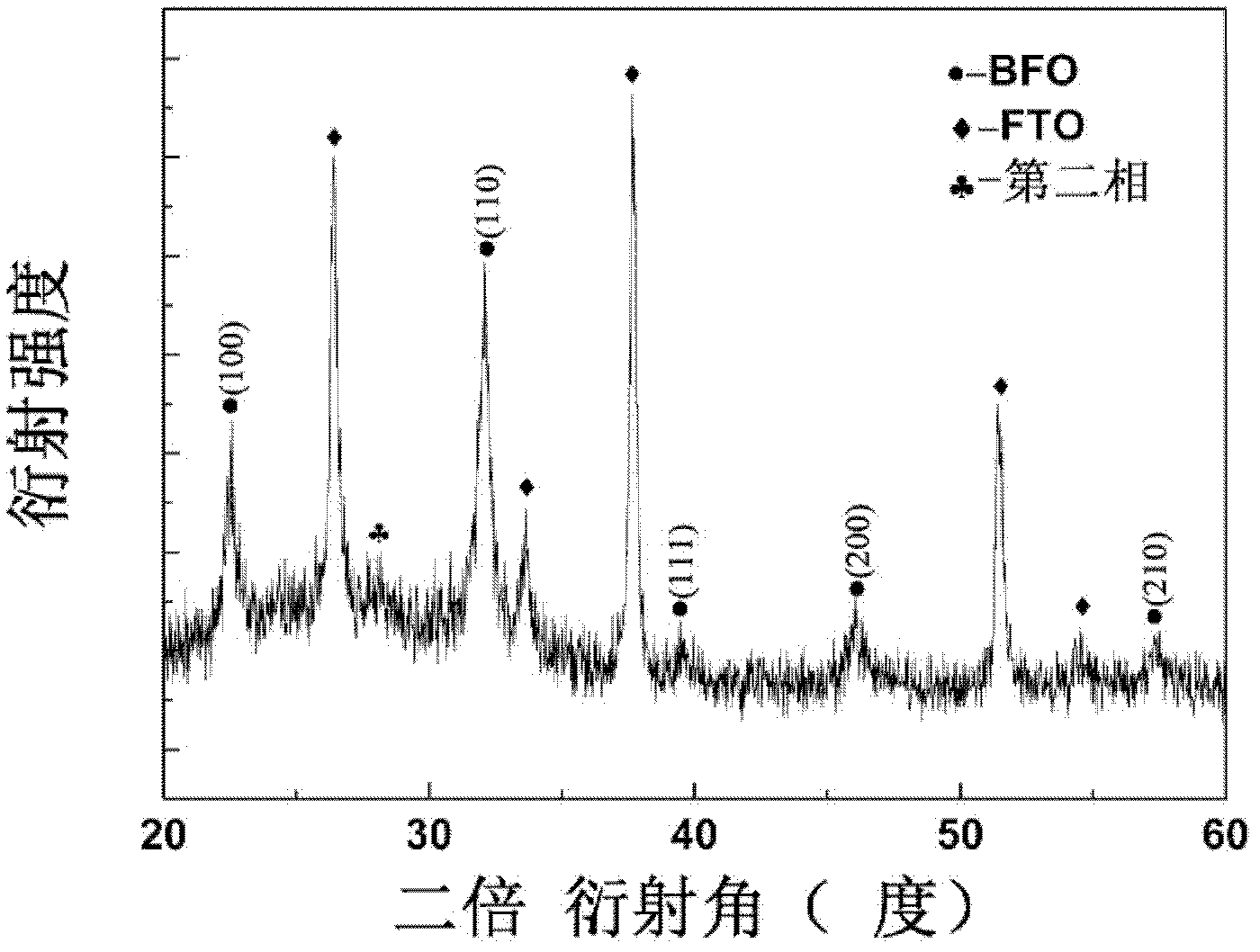
[0031] Bi(NO 3 ) 3 ·5H 2 O (excess 5%), Fe (NO 3 ) 3 9H 2 O is completely dissolved in ethylene glycol methyl ether at a molar ratio of 1:1, and a brownish-red clear and stable precursor solution is obtained. Films were then prepared by the gel-spin method. The condition of glue rejection is as follows: 10 seconds at 500 rpm and 30 seconds at 3000 rpm. After spinning the glue, the substrate with the precursor wet film was first dried on a hot plate at 200°C for 3 minutes, then calcined at 350°C for 5 minutes, and finally in O 2 Sintering at 500° C. for 5 minutes in a rapid annealing furnace under atmosphere. After the first layer was calcined, the first layer was annealed, and then annealed once every two layers, a total of 15 layers of glue were thrown, and the BFO ferroelectric thin film was obtained.

[0032] The prepared thin film is shielded by a mask plate with a hole of 0.5mm*0.5mm, and a 0.5mm*0.5mm Au upper electrode is deposited on the film surface by physica...

Embodiment 2

[0034] Bi(NO 3 ) 3 ·5H 2 O (excess 5%), Fe (NO 3 ) 3 9H 2 O is completely dissolved in ethylene glycol methyl ether at a molar ratio of 1:1, and a brownish-red clear and stable precursor solution is obtained. Films were then prepared by the gel-spin method. The condition of glue rejection is as follows: 10 seconds at 500 rpm and 30 seconds at 3000 rpm. After spinning the glue, the substrate with the precursor wet film was first dried on a hot plate at 200°C for 3 minutes, and then calcined at 350°C for 5 minutes. Finally at O 2 Sintering at 550° C. for 5 minutes in a rapid annealing furnace under atmosphere. After the first layer was calcined, the first layer was annealed, and then annealed once every two layers, a total of 15 layers of glue were thrown, and the BFO ferroelectric thin film was obtained.

[0035] The prepared thin film is shielded by a mask plate with a hole of 0.5mm*0.5mm, and a 0.5mm*0.5mm Au upper electrode is deposited on the film surface by physic...

Embodiment 3

[0037] Bi(NO 3 ) 3 ·5H 2 O (excess 5%), Fe (NO 3 ) 3 9H 2 O is completely dissolved in ethylene glycol methyl ether at a molar ratio of 1:1, and a brownish-red clear and stable precursor solution is obtained. Films were then prepared by the gel-spin method. The condition of glue rejection is as follows: 10 seconds at 500 rpm and 30 seconds at 3000 rpm. After spinning the glue, the substrate with the precursor wet film was first dried on a hot plate at 200°C for 3 minutes, and then calcined at 350°C for 5 minutes. Finally at O 2 Sintering at 600° C. for 5 minutes in a rapid annealing furnace under atmosphere. After the first layer was calcined, the first layer was annealed, and then annealed once every two layers, a total of 15 layers of glue were thrown, and the BFO ferroelectric thin film was obtained. The prepared thin film is shielded by a mask plate with a hole of 0.5mm*0.5mm, and a 0.5mm*0.5mm Au upper electrode is deposited on the film surface by physical sputte...


PUM


Abstract

The invention relates to a method for preparing a BiFeO3 ferroelectric thin film photovoltaic battery on a glass substrate, comprising the following steps of: selecting glass as a substrate; preparing a BiFeO3 ferroelectric thin film with a perovskite structure through a chemical solution deposition method; and preparing a top electrode with a size of 0.5*0.5 mm on the thin film through a physical sputtering method. Compared with the prior art, the method disclosed by the invention can be used for preparing the BiFeO3 ferroelectric and photovoltaic thin film with a perovskite structure, which has the advantages of high consistency and good repeatability on the glass substrate, by a low cost. The prepared thin film has the advantages of excellent photovoltaic property and single-directional conductive property of a diode. The BiFeO3 ferroelectric thin film can be applicable to the fields of a photovoltaic battery and an optical electronic device due to the excellent properties.

Description

technical field [0001] The invention belongs to the technical field of thin film deposition and photovoltaic cell preparation, and in particular relates to a method for preparing BiFeO on a glass substrate. 3 A method for ferroelectric thin film photovoltaic cells. Background technique [0002] Photovoltaic power generation is an effective way to utilize solar energy and an important part of renewable energy utilization. It is also the fastest growing, most dynamic, and most attention-grabbing research field in recent years. At present, the proportion of photovoltaic power generation in the entire energy structure is still very small (less than 1%), and the main reason is that the cost is too high. According to statistics, 65% of the cost of traditional crystalline silicon battery components comes from silicon wafers, which consumes a lot of silicon resources, and the supply of raw materials is tight, so it is difficult to meet the needs of large-scale promotion and applica...

Claims


Application Information

Patent Timeline
Patent Type & Authority Applications(China)
IPC IPC(8): H01L31/18C23C14/16C23C14/34
CPCY02P70/50
Inventor 郭益平郭兵李华刘河洲
Owner SHANGHAI JIAO TONG UNIV
Why Eureka
Try Eureka