Direct liquid cooling method for light emitting didoes and light emitting diode package utilizing method

A technology of light-emitting diodes and light-emitting diodes, which is applied in the field of cooling and heat dissipation, can solve the problems of reducing heat conduction efficiency, decreasing light energy efficiency, and fluorescent pink temperature difference, etc.

Inactive Publication Date: 2012-07-04
郑榕彬
View PDF5 Cites 0 Cited by
  • Summary
  • Abstract
  • Description
  • Claims
  • Application Information

AI Technical Summary

Problems solved by technology

In various heat conduction processes, different materials have different thermal conductivity coefficients, and it is easy to form a heat conduction bottleneck in materials with low conductivity coefficients (such as die-bonding glue), which reduces the efficiency of heat conduction
And the heat source of the LED chip is on the surface layer instead of the bottom, so the existing LED heat dissipation technology has inherent deficiencies
This indirect heat dissipation method also has great limitations in design (the heat source is on the light-emitting surface layer)—whether it is on the heat dissipation contact surface or the area and volume of the heat dissipation material—which leads to the accumulation of heat on the LED chip and the conversion of electrical energy. The light energy efficiency decreases, and the light attenuation continues to occur
In addition, since the silica gel of the fluorescent powder is closely attached to the light-emitting layer of the light-emitting diode, it absorbs a large amount of heat energy, which causes the light attenuation and color temperature difference of the phosphor powder due to long-term thermal decomposition.

Method used


Image

  • Direct liquid cooling method for light emitting didoes and light emitting diode package utilizing method
  • Direct liquid cooling method for light emitting didoes and light emitting diode package utilizing method
  • Direct liquid cooling method for light emitting didoes and light emitting diode package utilizing method

Examples


Embodiment Construction

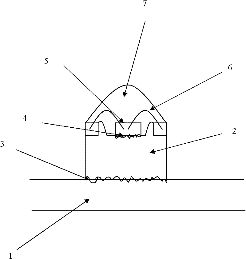
[0027] figure 1 A cross-section of existing heat dissipation techniques for light-emitting diodes is illustrated. Such as figure 1 As shown in , the reference numeral 1 denotes the aluminum substrate; the reference numeral 2 denotes the heat sink; the reference numerals 3 and 4 denote the silver paste; the reference numeral 5 denotes the LED chip; the reference numeral 6 denotes the wire; the reference numeral 7 denotes the silica gel phosphor.

[0028] As mentioned in the background technology, the heat dissipation technology of the light-emitting diodes in the prior art cannot ensure sufficient heat dissipation of the light-emitting diodes, which will lead to the accumulation of heat in the light-emitting diode chip, the current will continue to rise, and the light decay will continue to occur, and the phosphor powder will Long-term thermal decomposition results in light attenuation and color temperature differences.

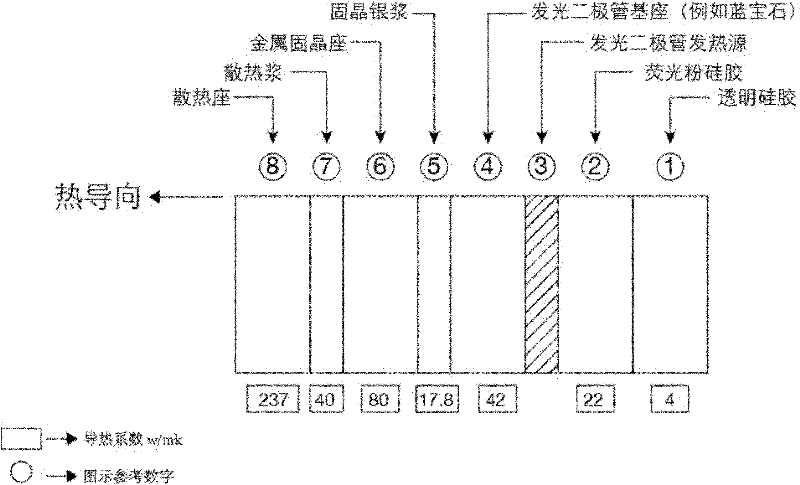
[0029] figure 2 The heat conduction relationship of ...


PUM


Abstract

The invention relates to a direct liquid cooling method for light emitting diodes and a light emitting diode package utilizing the method. The direct liquid cooling method includes: enabling non-conductive light-emitting liquid to be contacted with a light emitting diode and dissipating heat produced after the light emitting diode is powered on by means of liquid heat convection. In one embodiment, radiating fins are used in the method and the light emitting diode package for further heat conduction. The light emitting diode package utilizing the direct liquid cooling method has excellent heat radiation function, and decomposition, ageing, light attenuation and color shading due to the fact that the fluorescent powder is heated are weakened or eliminated.

Description

technical field [0001] In general, the present invention relates to cooling and heat dissipation of light emitting diodes. In particular, the present invention relates to a method for cooling LEDs by directly encapsulating one or more non-conductive and light-transmitting liquids on LED wafers, and LED packages using the method. Background technique [0002] Light-emitting diode (LED) is a light-emitting display device made of semiconductor materials that can directly convert electrical energy into light energy. It has the advantages of low power consumption and high brightness, so it is widely used in various electronic circuits, home appliances, Instruments and other equipment as indicators and display panels. Moreover, compared with ordinary incandescent lamps, light-emitting diodes have the advantages of small size, low calorific value, low power consumption, long life, fast response, environmental protection, etc., so they can also be widely used for lighting. [0003...

Claims


Application Information

Patent Timeline
Patent Type & Authority Applications(China)
IPC IPC(8): H01L33/48H01L33/64H01L33/56H01L33/50
CPCH01L33/648H01L33/48H01L33/64H01L33/483H01L33/50H01L33/56H01L2224/48091H01L2924/181H01L2924/00012H01L2924/00014
Inventor 郑榕彬
Owner 郑榕彬
Why Eureka
Try Eureka