
LC voltage-controlled oscillator (LC-VCO) with wide frequency tuning range

An LC-VCO, frequency tuning technology, applied in power oscillators, electrical components, etc., can solve the problems of reducing the equivalent Q value of switched capacitors, reducing the frequency tuning range, reducing phase noise performance, etc., to reduce fixed capacitor banks. number, easy process implementation, good effect of low phase noise

Active Publication Date: 2012-07-04
杭州中科微电子有限公司
View PDF2 Cites 13 Cited by
  • Summary
  • Abstract
  • Description
  • Claims
  • Application Information

AI Technical Summary

Problems solved by technology

[0004] Capacitor-switched broadband VCO can achieve a wide range of frequency tuning range, but when there are many switch-controllable capacitor banks, the parasitic capacitance introduced by switch-controllable capacitors will increase and reduce the frequency tuning range. In addition, because the Q value of the on-chip inductor varies with The frequency will vary greatly, so the value range of the switch controllable capacitor is limited by the value of the on-chip inductor
The disadvantages of capacitive switching broadband VCO are: (1) The frequency range is limited by inductance and parasitic capacitance
(2) When there are many switch-controllable capacitor banks, the on-resistance of the switch will reduce the equivalent Q value of the switched capacitor, thereby reducing the phase noise performance
The phase noise is better than -100dBc / Hz100kHz, the main disadvantage of this circuit is that it occupies a large chip area

Method used


Image

  • LC voltage-controlled oscillator (LC-VCO) with wide frequency tuning range
  • LC voltage-controlled oscillator (LC-VCO) with wide frequency tuning range
  • LC voltage-controlled oscillator (LC-VCO) with wide frequency tuning range

Examples


Embodiment 1

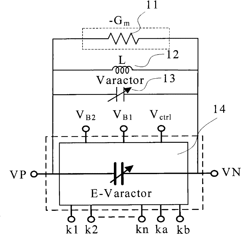
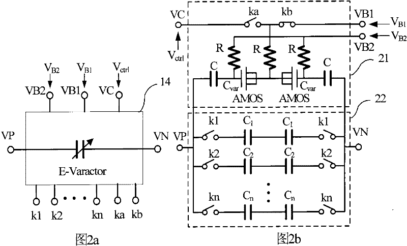
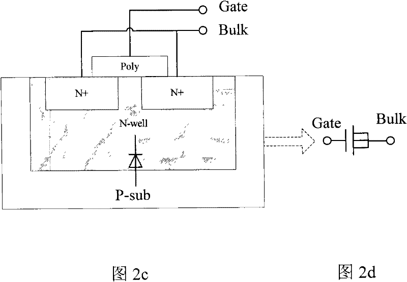
[0046] The equivalent resonant capacitor 14 of the VCO of the present invention is as Figure 2a as shown, Figure 2b for Figure 2a The schematic circuit diagram of the equivalent resonant capacitor 14 of the VCO of the present invention. The equivalent resonant capacitor circuit includes a switch-controlled variable capacitor 21 and a switch-controlled fixed capacitor 22, and the circuit adopts a differential symmetrical structure, C 1 , C 2 ,...,C n is a fixed capacitor, and k1, k2, ..., kn are control switches of the fixed capacitor. Like the traditional switched capacitor structure, C1-Cn and k1-kn form a switch-controlled fixed capacitor. Different from traditional switched capacitors, the switched variable capacitor of the present invention introduces an accumulative AMOS variable capacitor, and the control switches ka and kb are logic complementary MOS switches. When the switch ka is turned off, the switch kb is turned on. The voltage across the AMOS capacitor is...

no. 2 Embodiment

[0059] The embodiment of the present invention is based on an electrical schematic diagram of an LC-VCO with a wide frequency tuning range based on an equivalent resonant capacitor, as shown in 3a. NMOS transistors 308, 309 are cross-coupled with PMOS transistors 303, 302 to generate active negative resistance. The active negative resistance generated by the NMOS tube and the PMOS tube are respectively -Gmn and -Gmp. When the active negative resistance is greater than the resistance loss of the resonant circuit, the VCO meets the oscillation condition. The main variable capacitors in the circuit are 305 and 306, both of which have the same capacitance value, which is Cv. The capacitance of the variable capacitor varies with the control voltage V ctrl Variety. The inductor 304 is realized by the top layer metal in CMOS technology, and its structure is a spiral inductor, and its shape is quadrilateral. 307 in the circuit is an equivalent resonant capacitor, which has two fixe...

no. 3 Embodiment

[0069] Figure 4a The embodiment of the present invention is based on the electrical schematic diagram of the wide frequency tuning range LC-VCO of the equivalent resonant capacitor, as shown in Figure 4a shown. Such as Figure 4a structure with Figure 3a Basically the same, the difference is that in the equivalent resonant capacitor 407 circuit, there are three pairs of switch control signals for the fixed capacitor: k 1 、k 2 、k 3 ; In the circuit 407, kab is used as the control signal of the working module of the AMOS capacitor, and the two ends of the AMOS are biased with different voltages through kab, so as to work in different working ranges. The cross-coupling of NMOS transistors 408, 409 and PMOS transistors 403, 402 produces active negative resistance. The active negative resistance generated by the NMOS tube and the PMOS tube are respectively -Gmn and -Gmp. When the active negative resistance is greater than the resistance loss of the resonant circuit, the VC...


PUM


Abstract

The invention provides an LC voltage-controlled oscillator (LC-VCO) with a wide frequency tuning range based on an equivalent resonant capacitor; and the equivalent resonant capacitor of a differential circuit structure module comprises an accumulated variable capacitor (AMOS) with the bias voltage being controlled by a switch and a plurality of fixed capacitors which are controlled by the switches. In a high-frequency band, the bias voltage which is controlled by the switch enables the AMOS variable capacitor to work in an area in which the capacitor is not sensitive to the voltage; the AMOS capacitor is equivalent to the fixed capacitors, the noise which is introduced by a bias circuit is reduced, and a higher Q value is realized. In a low-frequency band, the bias voltage which is controlled by the switch enables the AMOS variable capacitor to work in a variable capacity interval, the proportion of the variable capacitance in the loop of the equivalent resonant capacitor is increased, the gains or the low-frequency band VCO are increased, so that the LC-VCO with low noise and the wide frequency tuning range is realized. Compared with an existing broad-band VCO, the wide frequency tuning range is realized to a circuit module with an appropriate amount of switch capacitance, and the LC-VCO with wide frequency tuning range has the characteristics of low power consumption and small chip area.

Description

technical field [0001] The invention relates to the technical field of wireless communication electronic circuits, relates to an inductance-capacitance voltage-controlled oscillator VCO, and in particular to a method for realizing a wide-frequency tuning range LC-VCO and a circuit module thereof. Background technique [0002] Multi-mode, multi-band receivers require VCO to have a large frequency tuning range, but the tuning range of on-chip LC is limited. Therefore, it is of great significance to study wideband VCO technology. The simplest technology to realize wideband VCO is to integrate two or more VCOs on the same chip, and the output of these VCOs selects one output through a multi-channel switch. Therefore, only one VCO is working at any time. This method can realize any Range of frequency output, but need to use multiple on-chip inductors, so the chip area is large, not suitable for engineering. Furthermore, by increasing the VCO voltage gain K VCO Wider bandwidth c...

Claims


Application Information

Patent Timeline
IPC IPC(8): H03B7/02
Inventor 肖时茂尹喜珍马成炎叶甜春殷明
Owner 杭州中科微电子有限公司
Learn More