Gold plating solution
A gold electroplating and gold electroplating technology, applied in the field of electrolytic gold electroplating solution, can solve problems such as instability of the electroplating solution, and achieve the effect of excellent corrosion resistance
- Summary
- Abstract
- Description
- Claims
- Application Information
AI Technical Summary
Problems solved by technology
Method used
Image
Examples
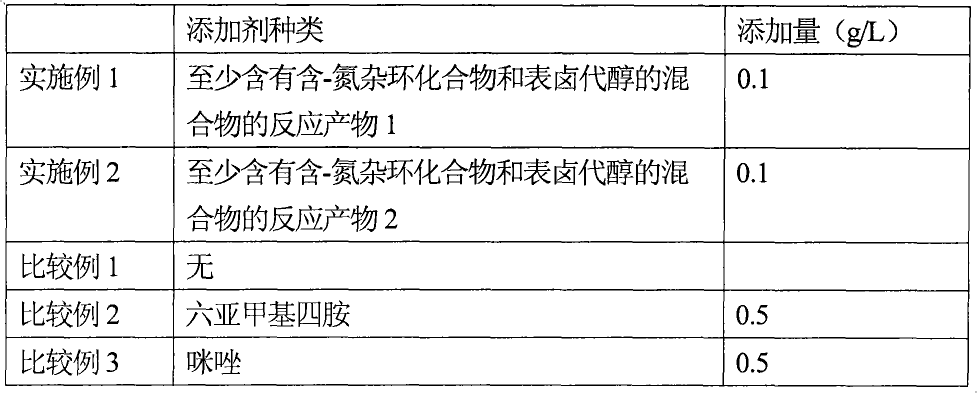
Embodiment 1-2 and comparative example 1-3
[0028] A gold-cobalt alloy plating solution containing the substances in Table 1 was prepared and subjected to a Hull cell test as shown below.
[0029] Potassium dicyanoalloy: 6g / L (4g / L as gold)
[0030] Basic cobalt carbonate solution: 10mL / L (250mL / L based on cobalt)
[0031] Tripotassium citrate monohydrate: 50g / L
[0032] Citric anhydride: 32g / L
[0033] Compounds in Table 1: Amounts listed in Table 1
[0034] Water (deionized water): balance
[0035] Hull battery test
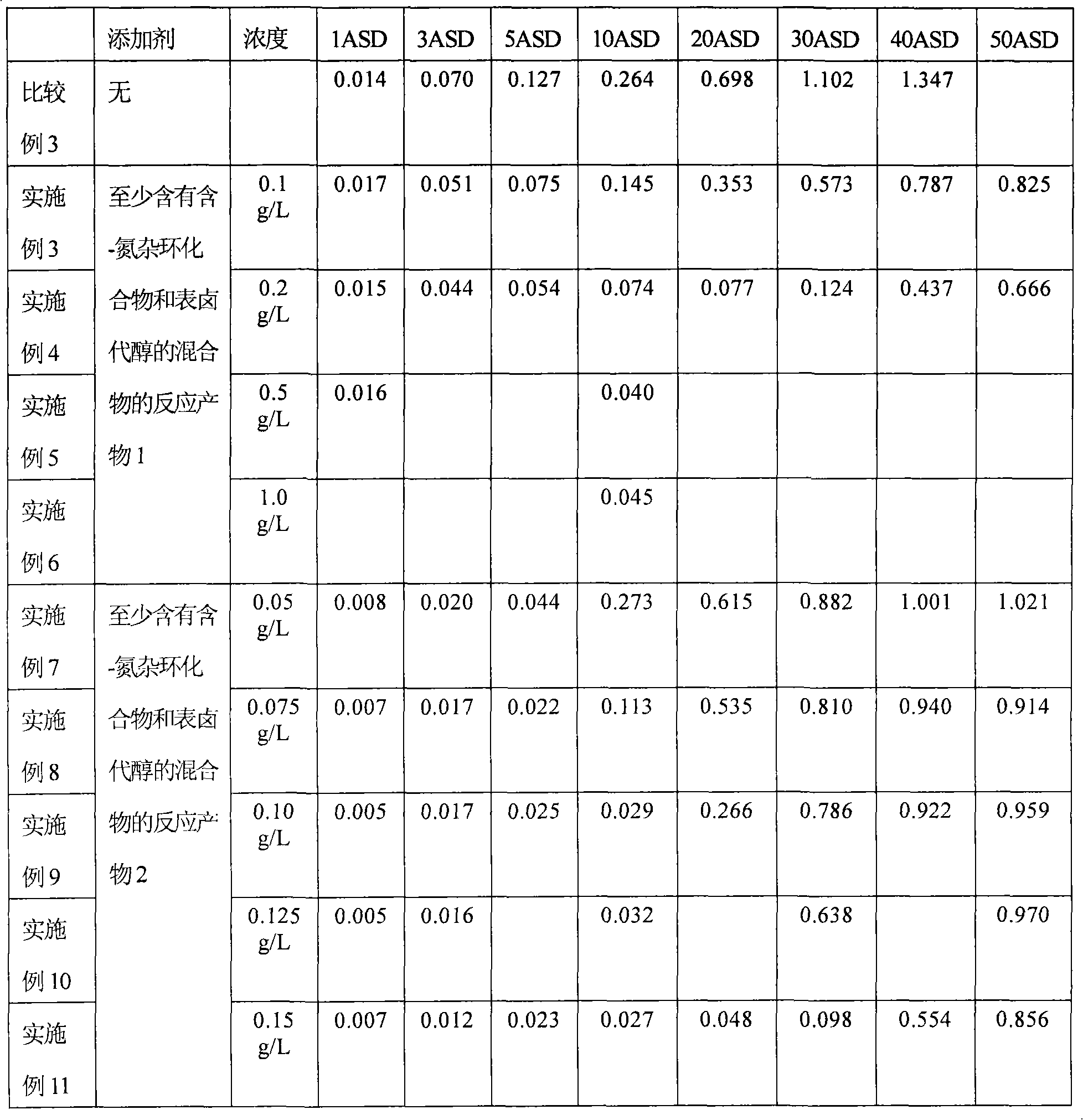
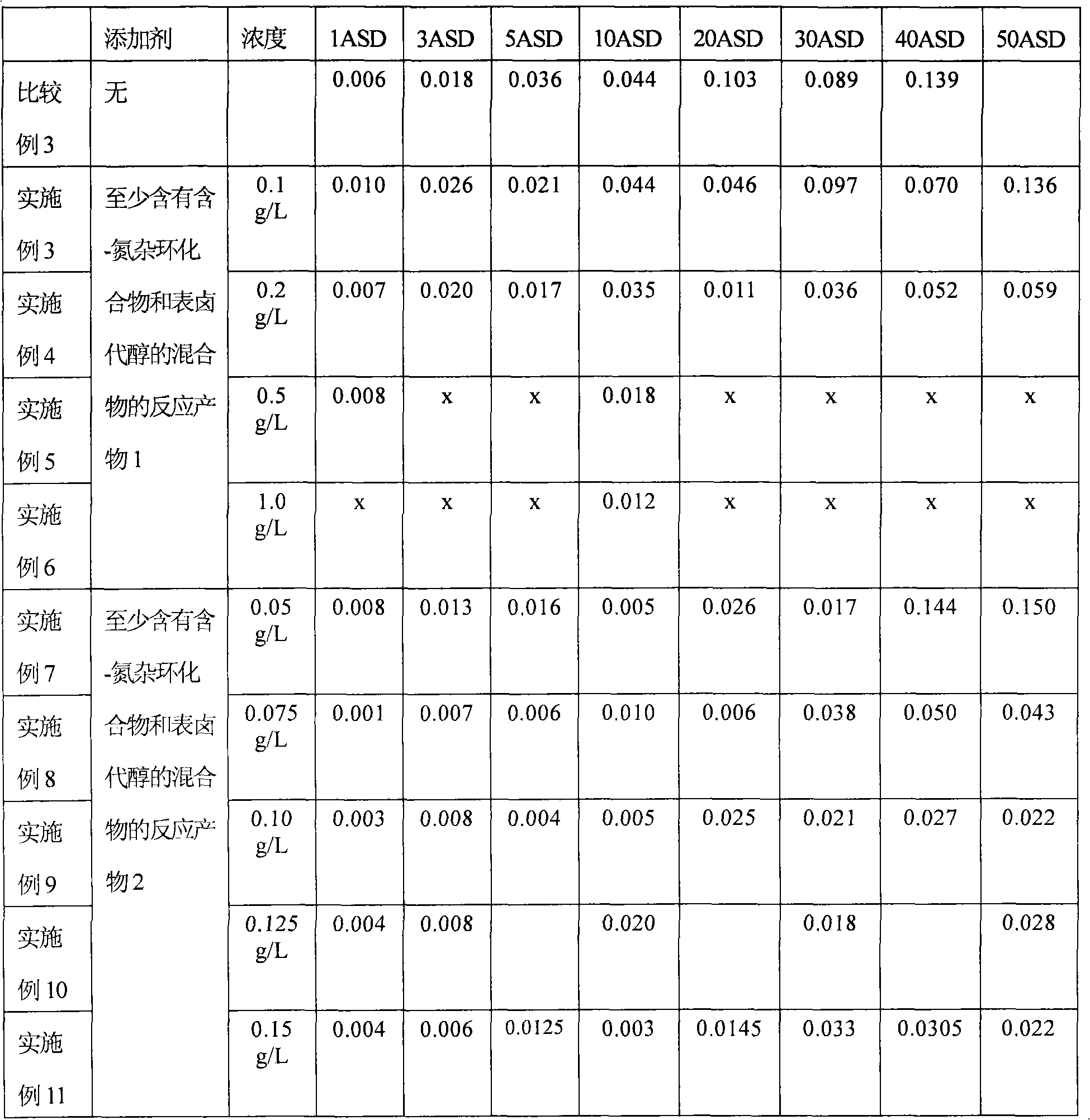
[0036] The Hull battery test was carried out using platinum-covered titanium as the insoluble anode, and the copper Hull battery plate as the cathode was nickel-plated by an anode rocker at a plating solution temperature of 50 °C and a stirring speed of 2 m / min. The current between cathode and anode was 1A (ampere) for 3 minutes. The results of the Hull cell tests and the profile of the Hull panels are listed in Tables 2 and 3. Here, the Hull cell test result means the thickness of the plating lay...
Embodiment 3-11, and comparative example 3
[0048] Spot tests were carried out with the electroplating baths prepared using the additives mentioned in the above examples.
[0049] point test
[0050] The copper plate is used as the material to be electroplated, and the electroplated nickel is deposited on the copper plate as an inner coating film. In order to verify the selective deposition of the gold electroplating film, the entire surface of the copper plate was covered with a layer of silicone rubber mask, and then part of the mask with a diameter of 10 mm was removed. However, between the nickel plating layer and the masking layer of the masking portion, by pressing a 0.5mm thick epoxy resin plate between the masking layer and the nickel plating layer around the edge of the exposed portion without masking, Along the edge of the uncovered portion, a notch with a width of 1.5 mm is formed. Therefore, when the plating solution is sprayed on the material to be plated, the plating solution may penetrate into the space...
Embodiment 12
[0057] The plating bath stability test was carried out by using an electroplating solution containing the additive used in Example 2 and a conventional plating solution (product name: RONOVEL TM CS-100 bath additives, available from Rohm and Haas Electronic Materials, LLC (Rohm and Haas Electronic Materials, LLC). 100 mL of each plating solution was prepared into 100 mL containers. The above vessel was heated to a water bath temperature of 50°C and then kept at room temperature for 19 hours. Repeat the process. After 0-5 days, the turbidity was measured by a nephelometer. The results are listed in Table 6. The unit is NTU.
[0058] Table 6
[0059]
[0060] As shown in the above examples and comparative examples, the gold plating film obtained by using the electroplating solution of the present invention can be deposited in the desired area, and the deposition in the undesired area is restricted, and the selective deposition is improved. In addition, compared with th...
PUM
| Property | Measurement | Unit |
|---|---|---|
| current density | aaaaa | aaaaa |
Abstract
Description
Claims
Application Information
 - R&D
- Intellectual Property
- Life Sciences
- Materials
- Tech Scout
- Unparalleled Data Quality
- Higher Quality Content
- 60% Fewer Hallucinations
Browse by: Latest US Patents, China's latest patents, Technical Efficacy Thesaurus, Application Domain, Technology Topic, Popular Technical Reports.
© 2025 PatSnap. All rights reserved.Legal|Privacy policy|Modern Slavery Act Transparency Statement|Sitemap|About US| Contact US: help@patsnap.com


