Processing method for engine crankshaft vibration damping pulley wheel hub with end surface rat fluted disc

A processing method, rattooth disc technology, applied in the field of crankshaft pulleys, can solve problems such as inability to effectively achieve easy assembly of the end of the crankshaft, failure to ensure the accuracy of the end of the crankshaft, and affect the accuracy of signal acquisition, etc., to achieve light weight, simple manufacturing process, low cost effect

Inactive Publication Date: 2012-07-25
WUHAN HONTRUST AUTO PULLEY IND
View PDF5 Cites 13 Cited by
  • Summary
  • Abstract
  • Description
  • Claims
  • Application Information

AI Technical Summary

Problems solved by technology

The existing vibration-absorbing pulley is generally fastened together with the end of the crankshaft by bolts. Once the assembly and debugging are completed, the bolts cannot be loosened, otherwise the accuracy of signal acquisition will be seriously affected.
The existing vibration-damping pulley is assembled with the end of the crankshaft, and the key connection is generally used to prevent relative sliding. The assembly of the key connection is relatively complicated, and at the same time, a high requirement is placed on the thickness of the center hole of the vibration-damping pulley, which requires that the vibration-damping pulley must use cast iron manufacturing
The application publication date is July 20, 2011, and the invention patent with the application publication number CN 102128246A discloses a spinning-formed engine shock absorber pulley ( figure 1 ), but this invention cannot guarantee the accuracy of synchronous operation with the end of the crankshaft, and cannot effectively achieve easy assembly with the end of the crankshaft

Method used


Image

  • Processing method for engine crankshaft vibration damping pulley wheel hub with end surface rat fluted disc
  • Processing method for engine crankshaft vibration damping pulley wheel hub with end surface rat fluted disc
  • Processing method for engine crankshaft vibration damping pulley wheel hub with end surface rat fluted disc

Examples


Embodiment Construction

[0021] The present invention will be further described below in conjunction with accompanying drawing:

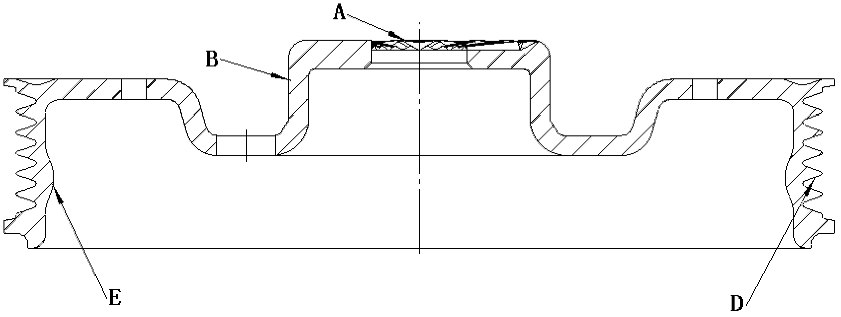
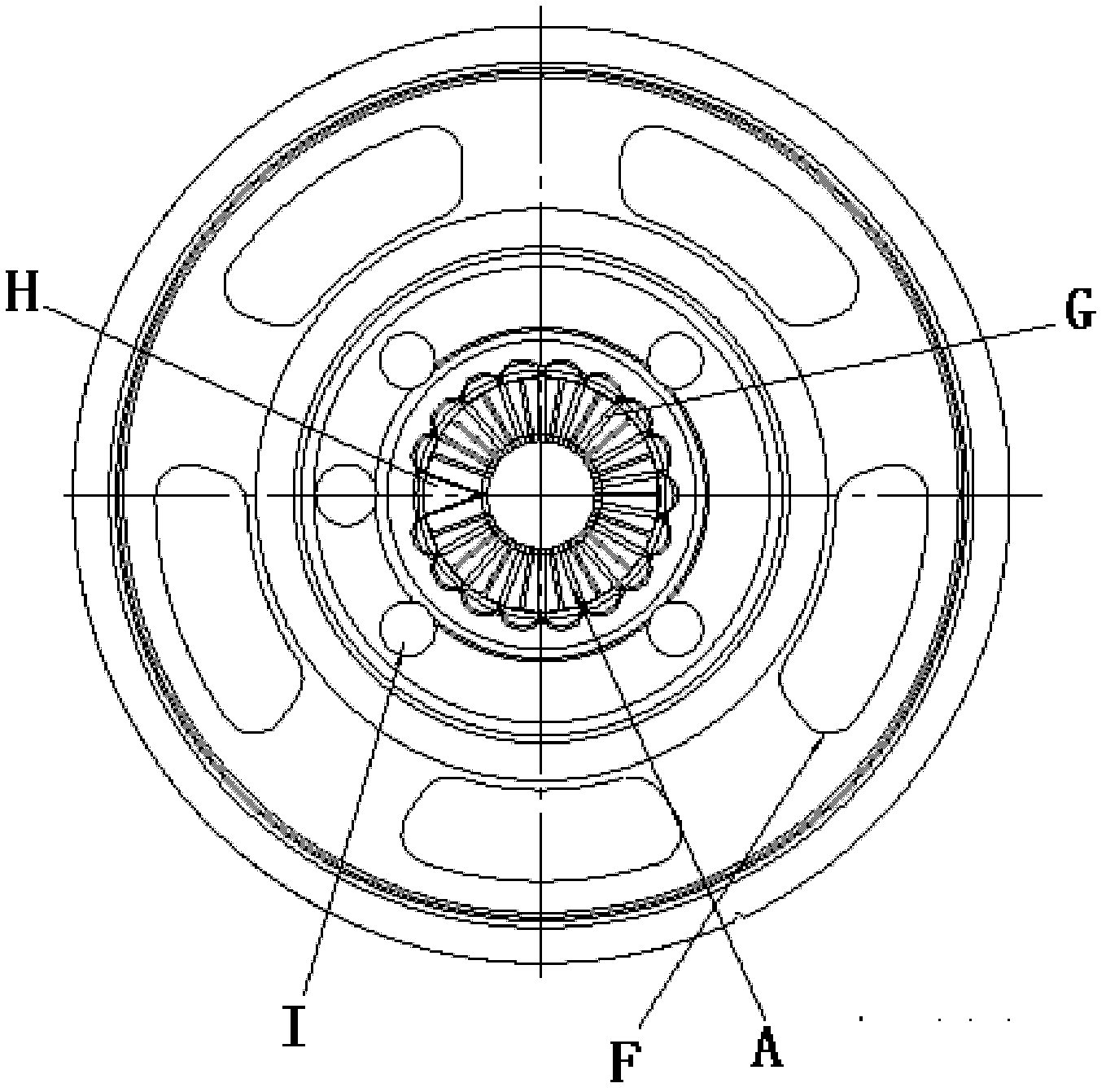
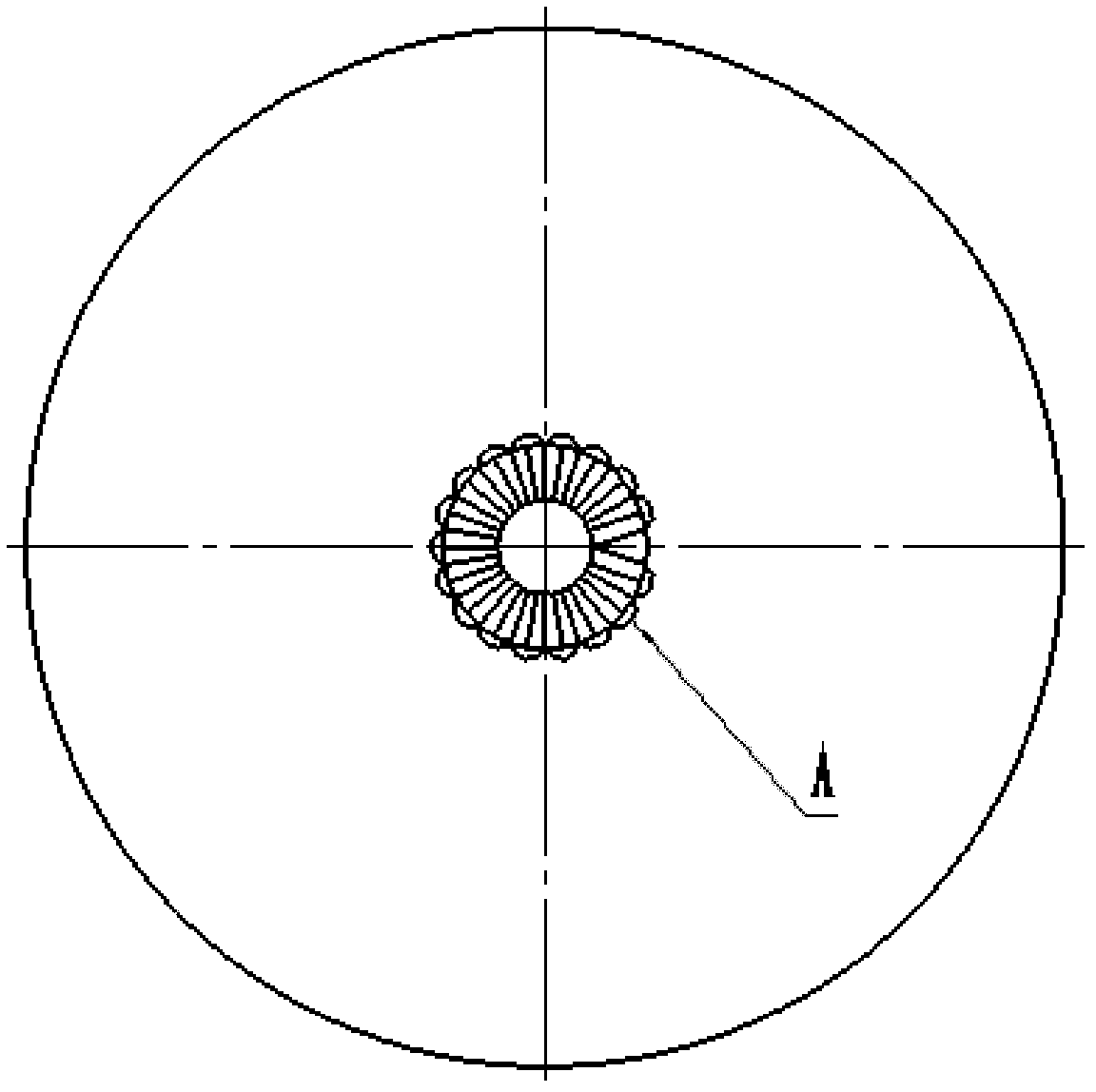
[0022] Such as figure 1 , figure 2 As shown, the product processed by the present invention includes an end-face rat tooth plate A, a columnar assembly surface B, a poly-wedge tooth D, an inner wall with an anti-slip protrusion annular assembly surface E, a mounting hole and a process hole F, wherein the end-face rat There are 17 mouse teeth G uniformly distributed at 20° on the disc A, and one mouse tooth G is missing on the 360° circumferential surface.

[0023] The processing method of the present invention is as follows: firstly, the most important end ratchet plate is spun out on the circular sheet material through the end face spinning technology, and then through further spinning, machining and punching processes, the engine crankshaft vibration damping plate is finally processed. The finished product of the pulley hub, the specific steps are as follows:

[0024]...


PUM


Abstract

The invention relates to a processing method for engine crankshaft vibration damping pulley wheel hub with end surface rat fluted disc. The specific steps are as follows: (1) processing an end surface rat fluted disc A on the metal circular sheet material by using end surface spinning technology; (2) processing a cylindrical assembling surface B at the outer side of the end surface rat fluted disc A by the spinning technology; (3) processing a curve C on the outer side radiation plate of the cylindrical assembling surface B by the spinning technology; (4) processing a multi-wedge tooth D on the blank excircle obtained in above procedures by the spinning technology; (5) processing an annular assembling surface E with an anti-slide bulge at the inner side of the multi-wedge tooth D by machining method; (6) punching a technological hole 1 and an installing hole F on the spoke. The processing method for engine crankshaft vibration damping pulley wheel hub with end surface rat fluted disc has the end surface rat tooth to be tightly engaged with the crankshaft tail, thus the transmission is precise and the transfer torque is larger; meanwhile, by fully using the spinning technology, the processing method is simple in manufacturing technique, convenient in installation and low in cost; at the same time, the processing method has small dynamic balance quantity, lowers noise of the engine and improves service life of the crankshaft.

Description

technical field [0001] The invention relates to a crankshaft pulley in an engine accessory transmission system, in particular to a processing method for an engine crankshaft vibration-damping pulley hub with an end rattoed disc. Background technique [0002] The engine electronic control system consists of sensors, electronic control unit ECU (Electronic Control Unit) and actuators. The sensor inputs the working state parameters of the engine into the electronic control unit ECU in the form of electronic signals and data. Gas and other systems issue corresponding signal commands to make the engine perform at its best. The sensor generally collects signals through a signal disc assembled with a vibration-absorbing pulley. With the development of the automobile industry, the accuracy of the signal collected by the sensor is getting higher and higher, which also puts forward higher and higher requirements for the synchronous operation of the vibration-absorbing pulley and the...

Claims


Application Information

Patent Timeline
Patent Type & Authority Applications(China)
IPC IPC(8): B21D53/26B21D22/14B21D28/30
Inventor 程涛宋学军汪啟福
Owner WUHAN HONTRUST AUTO PULLEY IND
Why Eureka
Try Eureka