Clamping system of movable main spindle box and clamping method

A spindle box and clamping oil cylinder technology, applied in the direction of large fixed members, metal processing machinery parts, metal processing equipment, etc., can solve the problems of affecting the processing quality and precision retention of parts, unable to detect clamping force, and inconvenient operation. Achieve the effects of improving processing quality and precision retention, facilitating automatic control, and reducing auxiliary time

Inactive Publication Date: 2012-07-25
TIANSHUI SPARK MACHINE TOOL
View PDF5 Cites 2 Cited by
  • Summary
  • Abstract
  • Description
  • Claims
  • Application Information

AI Technical Summary

Problems solved by technology

[0002] The processing technology of some slender shaft parts requires that the spindle box of the special machine tool can move along the direction of the bed rail and be accurately positioned at the position required by the processing technology. However, the rigidity of the slender shaft parts is poor. It is very easy to be unstable and deformed. At the same time, the rotation of the spindle chuck of the machine tool will cause the workpiece to vibrate, so that how to accurately maintain the positioning position of the spindle box will

Method used


Image

  • Clamping system of movable main spindle box and clamping method
  • Clamping system of movable main spindle box and clamping method
  • Clamping system of movable main spindle box and clamping method

Examples


Embodiment 1

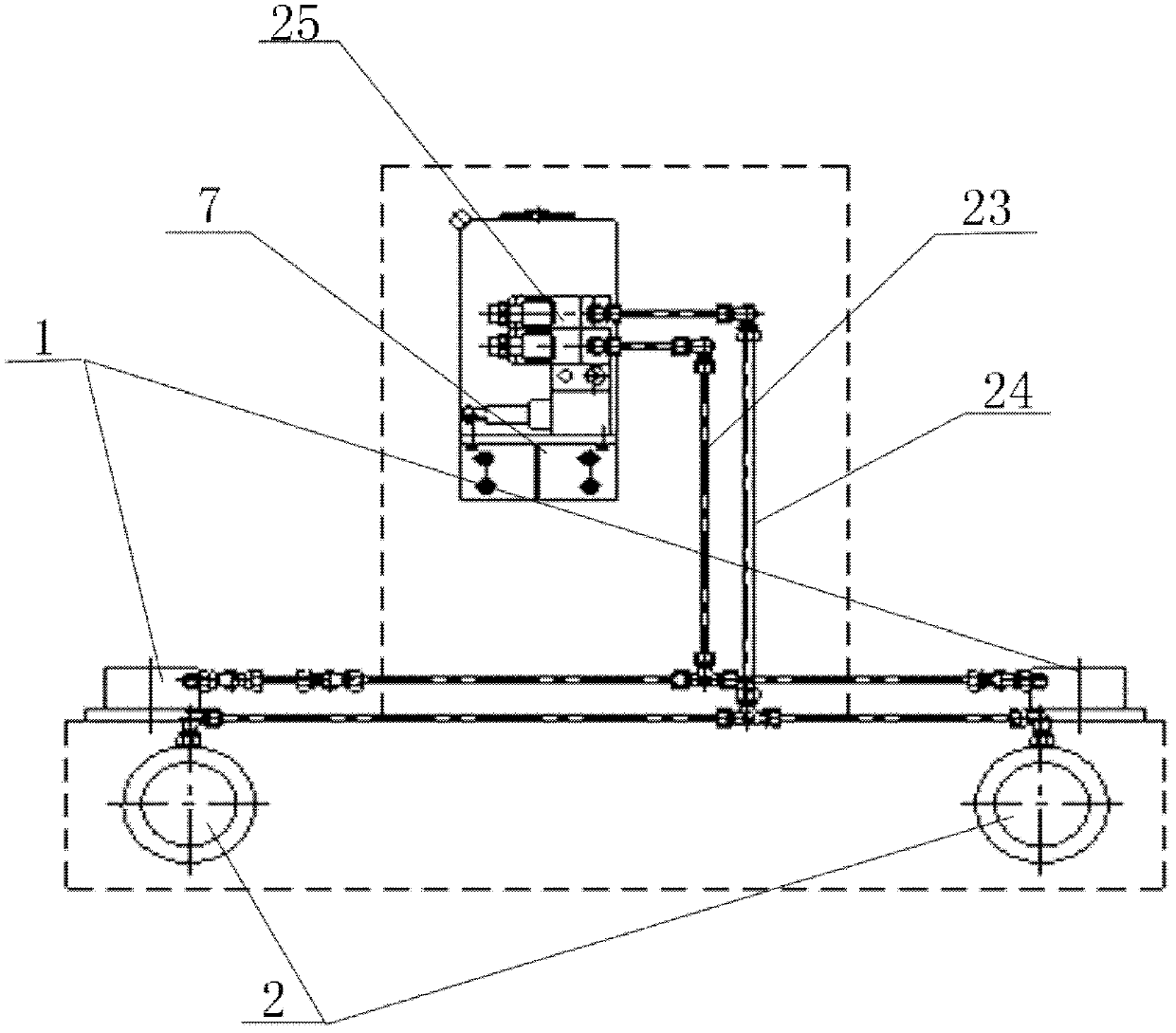
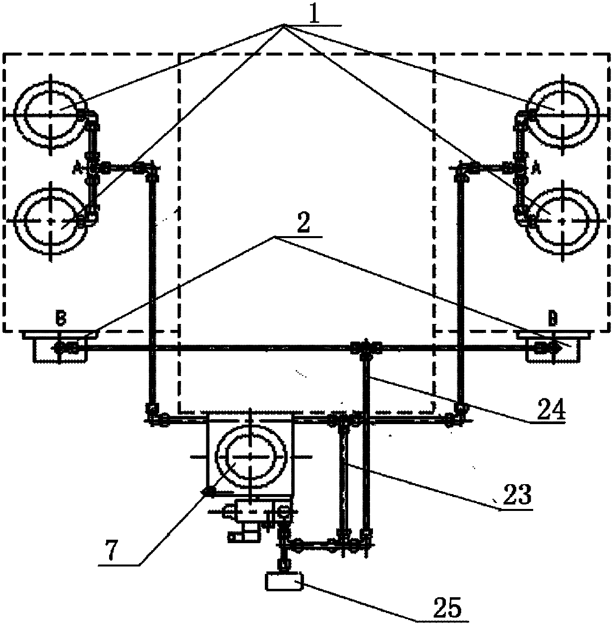
[0031] Example 1, such as figure 1 , figure 2 , image 3 , Figure 4 As shown, a clamping system for a movable spindle box includes two sets of first clamping cylinders 1 arranged in the vertical direction of the spindle box, and the first clamping cylinders include a pair of clamping cylinders; A pair of second clamping oil cylinders 2 are provided, and the first clamping oil cylinder 1 and the second clamping oil cylinder 2 are connected to each other through the first oil inlet and return pipeline 23, the second oil inlet and return pipeline 24 and the high-pressure pump station 7. Unicom, a solenoid valve group 25 is provided on the first oil inlet and return pipeline and the second oil inlet and return pipeline. By adjusting the pressure of the high-pressure pump station 7, the loosening strokes of the first clamping oil cylinder and the second oil cylinder can be adjusted.

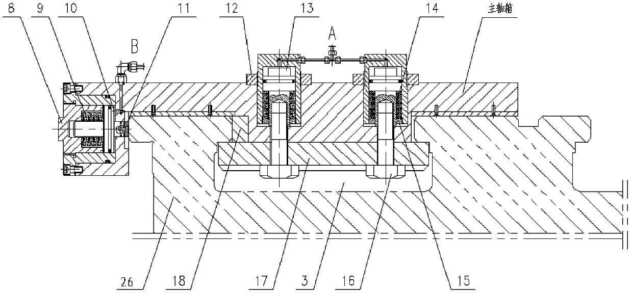
[0032] The first clamping cylinder 1 is provided with a first disc spring 14, and the first ...

Embodiment 2

[0037] Embodiment 2: as figure 1 , figure 2 , image 3 , Figure 4 As shown, the present invention also provides a clamping method for a movable headstock, comprising the following steps:

[0038] 1) Spindle box loosening steps:

[0039] The first electromagnetic reversing valve 19-1 controls the high-pressure pump station 7 to press the hydraulic oil into the first clamping cylinder 1 in the vertical direction through the first oil inlet and return pipeline 23, and the piston 13 of the first clamping cylinder goes down. The movement forces the first disc spring 14 to be compressed and deformed, and drives the T-shaped bolt 16 and the pressure plate 17 to move downward. At this time, the clamping force in the vertical direction of the spindle box disappears;

[0040] At the same time, the second electromagnetic reversing valve 19-2 controls the high-pressure pump station 7 to press the hydraulic oil into the second clamping cylinder 2 in the horizontal direction through t...


PUM


Abstract

The invention relates to a clamping system of a movable main spindle box, in particular to a clamping system of the movable main spindle box for special machine tools for manufacturing thin-long axial parts and a clamping method of the clamping system. The clamping system of the movable main spindle box comprises at least two groups of first clamping oil cylinders which are arranged along the vertical direction of the main spindle box, and at least one pair of second clamping oil cylinders which are arranged along the horizontal direction of the main spindle box, wherein each group of the first clamping oil cylinders comprises at least one pair of clamping oil cylinders; the first clamping oil cylinder and the second clamping oil cylinder are communicated with a high pressure pump station by a first oil inlet/return pipeline and a second oil inlet/return pipeline; and the first oil inlet/return pipeline and the second oil inlet/return pipeline are provided with electromagnetic valve control devices. The clamping method of the clamping system of the movable main spindle box is further provided. According to the clamping device and the clamping method disclosed by the invention, the clamping force along two directions of the main spindle box accurately keeps the locating position of the main spindle box, so that the manufacturing quality and the precision retentivity of parts are improved.

Description

Technical field: [0001] The invention relates to a clamping system of a movable spindle box, in particular to a clamping system and a clamping method of a movable spindle box for a special machine tool for processing slender shaft parts. Background technique: [0002] The processing technology of some slender shaft parts requires that the spindle box of the special machine tool can move along the direction of the bed rail and be accurately positioned at the position required by the processing technology. However, the rigidity of the slender shaft parts is poor. It is very easy to be unstable and deformed. At the same time, the rotation of the spindle chuck of the machine tool will cause the workpiece to vibrate, so that how to accurately maintain the positioning position of the spindle box will not be affected by the cutting force, workpiece gravity, centrifugal force or inertial force. When position changes and vibrations occur, how to ensure machining accuracy has become a...

Claims


Application Information

Patent Timeline
IPC IPC(8): B23Q1/28
Inventor 李维谦杨福年
Owner TIANSHUI SPARK MACHINE TOOL
Why Eureka
Try Eureka