Reflecting type grating light valve and processing method thereof

A technology of a grating light valve and a processing method, which is applied in the directions of diffraction grating, optics, optical components, etc., can solve the problems of low optical efficiency and extinction of the grating light valve, small size of the grating strip, complicated processing technology, etc. Small spot size and high image quality

Inactive Publication Date: 2012-07-25
方平
View PDF5 Cites 5 Cited by
  • Summary
  • Abstract
  • Description
  • Claims
  • Application Information

AI Technical Summary

Problems solved by technology

Therefore, although the device is manufactured using mature photolithography and wet and dry etching methods, due to the small size and high precision of the grating strips, the processing technology is still complicated and the yield is low.
At the same time, th

Method used


Image

  • Reflecting type grating light valve and processing method thereof
  • Reflecting type grating light valve and processing method thereof
  • Reflecting type grating light valve and processing method thereof

Examples


Embodiment

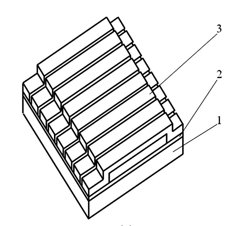
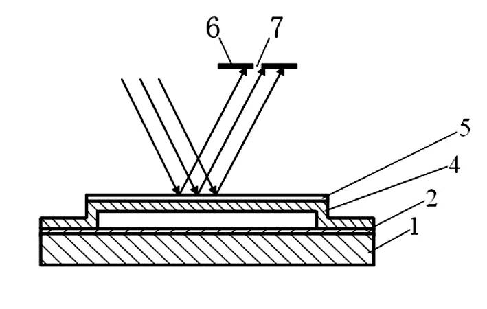
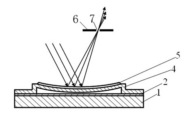
[0040] In this embodiment, the number of movable grating bars is 512, the thickness of the silicon substrate 1 is 300 μm, the thickness of the silicon dioxide layer 2 is 0.6 μm, the thickness of the silicon nitride beam 4 is 200 nm, the width is 50 μm, and the length is 200 μm. The distance between the silicon oxide beam 4 and the silicon dioxide layer 2 is 1 μm, the thickness of the metal reflection layer 5 is 60 nm, the width is 50 μm, and the length is 200 μm, the distance between two adjacent movable grating bars is 1 μm, and the width of the slit 7 is It is 5 μm and the length is 30 mm. Experimental results show that the reflective grating light valve 10 of the embodiment of the present invention has a light efficiency of 75%, an extinction ratio of 50:1, and an operating frequency of 300 kHz.

[0041]The reflective grating light valve 10 of the embodiment of the present invention is applied to high-resolution laser engraving equipment as a multi-channel light modulation ...


PUM

PropertyMeasurementUnit
Thicknessaaaaaaaaaa
Widthaaaaaaaaaa
Lengthaaaaaaaaaa

Abstract

The invention relates to a reflecting type grating light valve and a processing method thereof. The reflecting type grating light valve mainly comprises a silicon substrate, a silicon dioxide layer and removable grating strips, wherein the silicon dioxide layer is arranged on the silicon substrate, a plurality of removable grating strips are arranged on the silicon dioxide layer, and the removable grating strips are mutually parallel and are also arranged in an equally spaced way; the removable grating strips are in a bridge shape with a suspended middle, and both ends of the removable grating strips are respectively fixed on the silicon dioxide layer. The processing method comprises the following steps that: the silicon dioxide layer is grown on the silicon substrate, a silicon sacrifice layer is grown on the silicon dioxide layer, and a silicon nitride layer is grown on the silicon sacrifice layer; the operation of ion etching is carried out on the silicon nitride layer by using an ion etching method, and a silicon-nitride beam part is remained; the operation of erosion is carried out on the sacrifice layer by using a chemical erosion method, the sacrifice layer is emptied, and a silicon-nitride beam with a suspended middle is obtained, wherein both ends of the silicon-nitride beam are fixed on the silicon dioxide layer; and the surface of the silicon nitride layer is evaporated with a layer of metallic aluminum or metallic silver as a metal reflecting layer and an upper electrode; the reflecting type grating light valve has high light efficiency, high extinction ratio and high response speed; and moreover, the reflecting type grating light valve has a simple processing process, can be used as a multi-path light modulating component of high-resolution laser engraving equipment and is applied to the high-resolution laser engraving equipment in the fields of high-quality printing and anti-counterfeiting packaging.

Description

technical field [0001] The invention relates to a reflective grating light valve and a processing method thereof, belonging to the field of optoelectronic technology. Background technique [0002] High-resolution laser engraving equipment is widely used in the fields of high-quality printing and anti-counterfeiting packaging, and has the characteristics of high resolution and fast scanning speed. Laser engraving equipment generally adopts micro-electromechanical processing multi-channel light modulation devices, which are required to have high optical efficiency, extinction ratio and response speed. There are mainly two types of micro-electro-mechanical multi-channel light modulation devices in the prior art. [0003] One is a light deflection device based on a cantilever beam or hinge structure, typically a DMD device from Texas Instruments. The deflection of the rotating mirror of the DMD device is large, and the natural frequency of the cantilever beam and the hinge str...

Claims


Application Information

Patent Timeline
IPC IPC(8): B41J2/435G02B5/18G02B26/00
Inventor 方平
Owner 方平
Why Eureka
Try Eureka