Optical lens with free-form surfaces for LED automobile headlight

An optical lens, high beam technology, applied in optics, condenser mirrors, headlights, etc., can solve the problems of compressed optical system volume, complex optical system, difficult to control glare effect, etc.

Active Publication Date: 2012-07-25
SOUTH CHINA UNIV OF TECH
View PDF4 Cites 20 Cited by
  • Summary
  • Abstract
  • Description
  • Claims
  • Application Information

AI Technical Summary

Problems solved by technology

Refractive LED headlight modules are usually composed of a light source and a light distribution lens. The light emitted from the light source passes through the light distribution lens and forms a predetermined light pattern on the receiving screen. The light distribution through the lens can effectively reduce the glare effect , the volume of the optical system is compressed, and the optical system also has a high energy utilization rate; the reflective LED headlight is generally composed of a light source and a reflector, and a single reflector is used to comp

Method used


Image

  • Optical lens with free-form surfaces for LED automobile headlight
  • Optical lens with free-form surfaces for LED automobile headlight
  • Optical lens with free-form surfaces for LED automobile headlight

Examples


Embodiment Construction

[0048] The specific implementation of the present invention will not be described below in conjunction with the accompanying drawings and Examples, but the implementation and protection of the present invention are not limited thereto.

[0049] 1. Set the initial conditions and evenly divide the solid angle of the light source

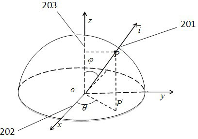
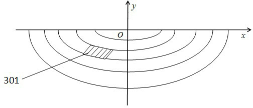
[0050] First, the distance between the target lighting surface and the LED is 25m. For the high beam, the target lighting area is set to be a partial ellipse with a major semi-axis of 4m and a minor semi-axis of 3m. For example image 3 As shown, it is a division diagram of an elliptical ring in the high beam target area, where 301 is a semi-elliptical ring area below the horizontal line, and a large number of ring areas together form a high beam lighting area. The total luminous flux of the LED light source is 300lm, and the light intensity of the LED center is 95.4930cd. figure 2 Shown is the spherical coordinate diagram of the LED light source in ...


PUM


Abstract

The invention discloses an optical lens with free-form surfaces for an LED automobile headlight. The optical lens is made of a transparent material, the transparent material is PC (polycarbonate) or PMMA (polymethyl methacrylate) or optical glass, and the lens consists of an incident surface and an emergent surface. A cavity is disposed in the center of the bottom of the lens, an LED is mounted in the cavity, a part of the wall of the cavity is a cylindrical surface, the incident surface consists of the cylindrical surface and the free-form surface positioned on the top of the cylindrical surface, the outer side surface of the lens is the other free-form surface, and the top of the lens is a plane, namely the emergent surface. Light rays emitted from a light source almost can be completely collected and used due to the fact that luminous efficiency of the LED light source is high and the lens with the free-form surfaces is adopted, energy utilization rate is high, and the luminous direction can be controlled due to a light form of the LED light source. In addition, the cavity is arranged in the middle of the bottom of the lens, the LED is mounted in the cavity, accordingly, the LED light source can be installed easily, the size of the lens is small, and a large space is reserved to facilitate installation of a radiating device. Besides, the LED light source is turned on, the light rays are emergent via the lens, the elliptical light form can be obtained, and the requirement of illuminance distribution of the national standards GB25991-2010 is met.

Description

technical field [0001] The invention relates to the technical field of LED car lamp lighting, in particular to a free-form surface optical lens used for LED car high beams. Background technique [0002] Light-emitting diodes (LEDs) are the fourth generation of automotive light sources following incandescent lamps, tungsten-halogen lamps and high-intensity discharge lamps (HID). LED has many advantages such as small size, low energy consumption, fast response, and long life, and conforms to the trend of future automobile development in the direction of compactness, energy saving, safety, and fashion. In recent years, with the continuous expansion of the application of LEDs in automotive lighting systems, more and more problems have been overcome. However, the application of LEDs in automotive headlights is still challenging, that is, the optical characteristics of LEDs are different from traditional automotive light sources, which makes LEDs face complex optical design when ...

Claims


Application Information

Patent Timeline
IPC IPC(8): F21V5/04F21W101/02F21Y101/02F21W107/10
CPCG02B19/0061G02B19/0014F21V5/04F21S48/00F21S41/143F21S41/255
Inventor 王洪吴衡黄华茂陈赞吉杨洁
Owner SOUTH CHINA UNIV OF TECH
Why Eureka
Try Eureka