Heat sink for electronic device, and process for production thereof

A technology for electronic equipment and manufacturing methods, applied in metal processing equipment, chemical instruments and methods, cooling/ventilation/heating transformation, etc., can solve problems such as rising material costs, and achieve the effect of excellent thermal conductivity and thin thickness

Active Publication Date: 2012-07-25
JFE PRECISION CORP
View PDF6 Cites 11 Cited by
  • Summary
  • Abstract
  • Description
  • Claims
  • Application Information

AI Technical Summary

Problems solved by technology

In order to form a Cu layer free from defects caused by such shrinkage cavities, it is necessary to increase the

Method used


Image

  • Heat sink for electronic device, and process for production thereof
  • Heat sink for electronic device, and process for production thereof
  • Heat sink for electronic device, and process for production thereof

Examples


Example Embodiment

[0096] Example 1

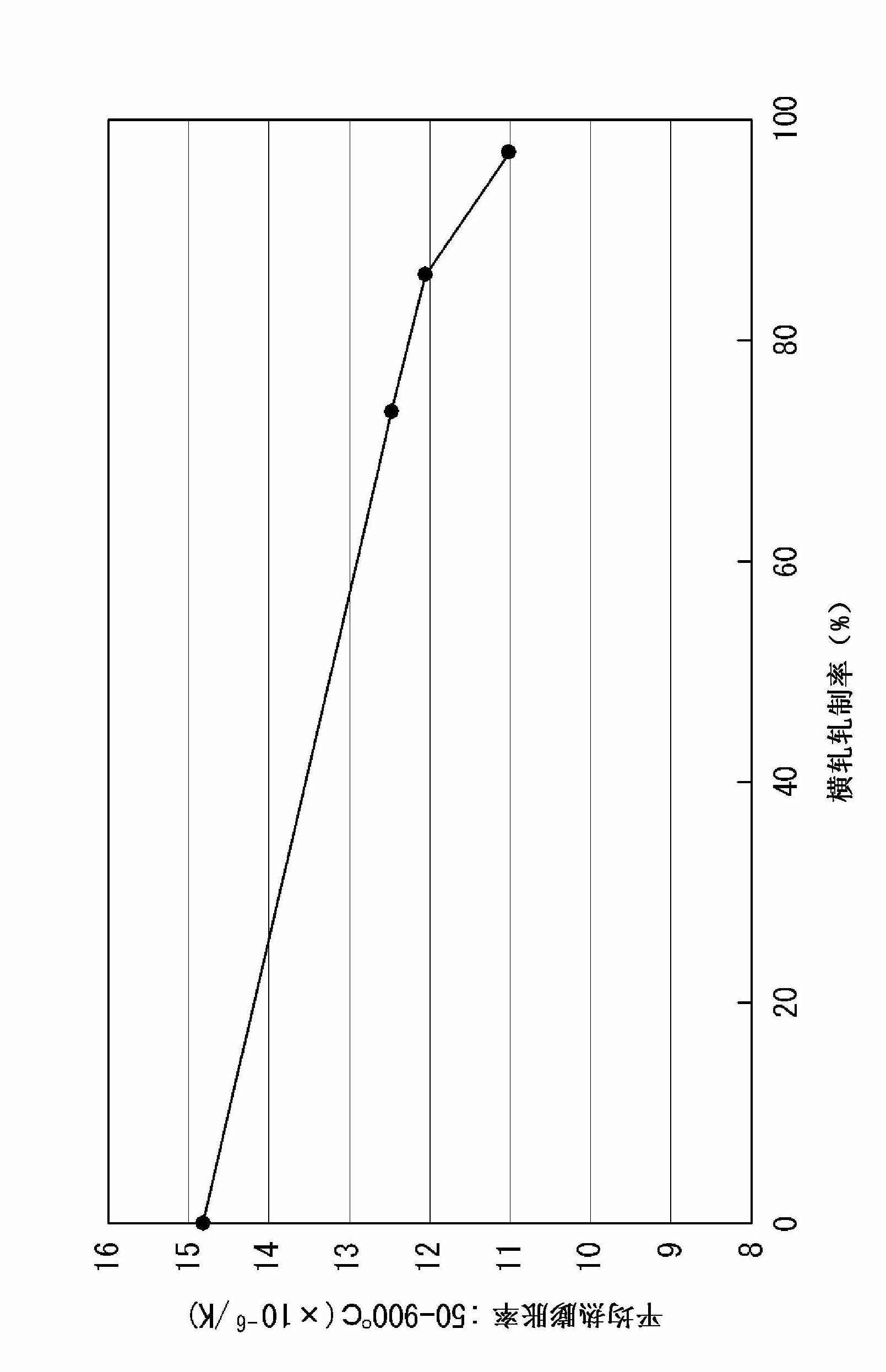
[0097] The Cr-Cu alloy sheet was cold-rolled and cross-rolled with the same rolling rate in both rolling directions, and reduced to a thickness of 0.05 mm (rolling rate: 98.3%), thereby obtaining a Cr-Cu alloy sheet . A 65mm square size was cut out from the rolled sheet. Two pieces of this rolled Cr-Cu alloy plate were superimposed into a set to form 4 layers, and 5 pure copper (same size and thickness: 0.1mm as the Cr-Cu alloy material) plate according to the pure copper plate (1 piece), The Cr-Cu alloy plates (two stacked in a set) are stacked alternately in order, and the spark plasma sintering (SPS) device [DR.SINTER SPS-1050 manufactured by Sumitomo Carbon Mining Co., Ltd.] is kept at 900°C for 40 minutes. Diffusion bonding was performed under a pressure of 20 MPa to obtain a Cr-Cu alloy / Cu laminate.

[0098] It was confirmed that after heat-treating the test piece cut from the obtained diffusion bonded sheet at 600°C (holding time: 120 minutes), the ther...

Example Embodiment

[0102] Example 2

[0103] The Cr-Cu alloy plate is cold rolled to a thickness of 0.10mm (rolling rate: 96.7%) to obtain a Cr-Cu alloy plate. The rolled Cr-Cu alloy plate is 4 pieces, and the pure copper plate (1 Except that the order of the Cr-Cu alloy plate (1 sheet) and the Cr-Cu alloy plate (1 sheet) were alternately overlapped, the same as in Example 1 was carried out to obtain a Cr-Cu alloy / Cu laminate.

[0104] It was confirmed that after the test piece cut from the obtained Cr-Cu alloy / Cu laminate was heat-treated at 600°C (holding time: 120 minutes), the thickness of the thermal conductivity in the thickness direction was measured by the laser flash method. The thermal conductivity in the direction is 230W / mK, and the thermal conductivity in the surface direction is 298W / mK, which has excellent heat dissipation. In addition, the average thermal expansion coefficient of 50~900℃ is 12.5×10 -6 / K, the thermal expansion rate can still be obtained without hindering the brazing ...

Example Embodiment

[0105] Example 3

[0106] The Cr-Cu alloy plate is cold rolled to a thickness of 0.15mm (rolling rate: 95.0%) to obtain a Cr-Cu alloy plate. The rolled Cr-Cu alloy plate is 4 pieces, and the pure copper plate (1 Except that the order of the Cr-Cu alloy plate (1 sheet) and the Cr-Cu alloy plate (1 sheet) were alternately overlapped, the same as in Example 1 was carried out to obtain a Cr-Cu alloy / Cu laminate.

[0107] It was confirmed that after the test piece cut from the obtained Cr-Cu alloy / Cu laminate was heat-treated at 600°C (holding time: 120 minutes), the thickness of the thermal conductivity in the thickness direction was measured by the laser flash method. The thermal conductivity in the direction is 195W / mK, and the thermal conductivity in the surface direction is 280W / mK, which has excellent heat dissipation. In addition, the average thermal expansion coefficient at 50~900℃ is 11.6×10 -6 / K, the thermal expansion rate can still be obtained without hindering the brazing ...


PUM

PropertyMeasurementUnit
Long trailaaaaaaaaaa
Thermal conductivityaaaaaaaaaa

Abstract

Disclosed is a heat sink for an electronic device, produced by joining a Cr-Cu alloy sheet comprising a Cu matrix and more than 30 mass% and not more than 80 mass% of Cr to a Cu sheet, and rolling the joined product, thereby producing a laminate having a Cr-Cu alloy layer and a Cu layer. The heat sink for an electronic device has low heat expansion properties, excellent heat conductivity particularly in the direction of thickness, and a reduced entire thickness.

Description

technical field [0001] The present invention relates to a suitable heat sink (heat sink material) used for rapidly dissipating heat generated from a heat generating body such as a semiconductor element mounted in an electronic device and a manufacturing method thereof, and particularly relates to the realization of low thermal expansion coefficient and high thermal conductivity An advantageous improved heat sink for electronic equipment and a manufacturing method thereof. Background technique [0002] High-output power semiconductor components are used in inverters of hybrid vehicles and the like, and demand has rapidly increased in recent years. [0003] In this power semiconductor component, a semiconductor is usually bonded to a ceramic substrate. As ceramic substrates, there are known laminated substrates (DBC substrates) obtained by metallizing alumina ceramics with copper (DBC substrates) or laminated substrates obtained by metallizing aluminum nitride with aluminum (...

Claims


Application Information

Patent Timeline
IPC IPC(8): H01L23/373
CPCC22C27/06B22F3/26B22F7/02C22C1/0425C22F1/08H01L23/3735C22F1/11B22F1/0055C22C1/045H01L23/473C22C30/02C22F1/18B22F2007/045B21B3/00B32B15/01C22C9/00B22F7/04H01L23/3736H01L2224/32225H05K7/20H01L23/36H01L23/373
Inventor 寺尾星明小日置英明
Owner JFE PRECISION CORP
Why Eureka
Try Eureka