Radio-frequency emission front-end circuit with automatic gain control

A technology of automatic gain control and automatic control circuit, applied in the field of radio frequency communication, can solve the problems of working state change, output signal-to-noise ratio reduction, insensitivity to amplitude change, etc., to improve stability and response speed, and improve system signal-to-noise ratio. , the effect of optimizing the system design

Active Publication Date: 2012-08-01
中科芯未来微电子科技成都有限公司
View PDF4 Cites 25 Cited by
  • Summary
  • Abstract
  • Description
  • Claims
  • Application Information

AI Technical Summary

Problems solved by technology

This form can obtain greater gain at a very high frequency with less power consumption, but its disadvantage is that the load will vary greatly with the process angle and temperature, so the amplitude of the output signal depends on the chip consistency and resistance to the environment (temperature) The performance of the change characteristics is poor. In order to obtain a relatively stable output power, it is necessary to correct the amplitude of the circuit
[0005] There are many disadvantages in the prior art fixed-gain transmitter: First, the traditional control method using a radio frequency fixed-gain transmitter can only be suitable for applications that are not sensitive to changes in output signal amplitude or have low requirements for output signal amplitude changes occasion
Second, the traditional design does not consider that the RF gain can be adjusted. The actual problem is that when the output signal is large, it is easy to saturate the RF chips of other systems, which cannot meet the requirements that the output signal in the wireless communication system cannot cause interference to other systems.
Third, in the traditional system design, since the gain of the front end of the system is set at a fixed gain, when the designed gain meets a certain requirement, the corresponding receiving system can correctly receive and demodulate the RF signal, but the actual application It may be an application that changes with temperature. The direct result of temperature change is that the working state of the design circuit in the RF transmitter chip changes. The main consequence is that the output amplitude changes accordingly. If the output amplitude is due to temperature Changes and decreases, it is possible that the original design cannot meet the requirements, so the corresponding receiver system will be affected, resulting in a decrease in the output signal-to-noise ratio

Method used


Image

  • Radio-frequency emission front-end circuit with automatic gain control
  • Radio-frequency emission front-end circuit with automatic gain control
  • Radio-frequency emission front-end circuit with automatic gain control

Examples


Embodiment Construction

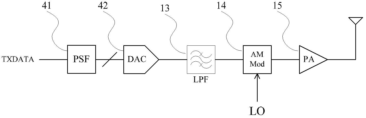
[0028] The radio frequency transmitting front-end circuit with automatic gain control of the present invention can be used in radio frequency receivers that have high requirements on system output amplitude changes and other system designs that require transmitted output signals to vary within a small range. In addition to the gain amplification of traditional transmitters and the function of driving 50 load, it also has the functions of RF variable gain amplifier and RF variable gain modulator, which can better reduce hardware and system power consumption and improve system signal-to-noise ratio. Optimize system design. The typical structural block diagram of the traditional transmission chain is as follows: figure 1As shown, the signal to be transmitted passes through the digital Gaussian shaping filter circuit 41, and is reshaped and encoded into Manchester or other encoding formats. Through this filtering, the energy of the digital signal can be mainly concentrated in a sy...


PUM


Abstract

The invention discloses a radio-frequency emission front-end circuit with automatic gain control, which comprises a radio-frequency variable gain power amplifier, a radio-frequency variable gain modulator and a radio-frequency amplitude detection automatic control circuit, wherein the radio-frequency variable gain power amplifier is composed of a first-level variable gain amplifier and a fixed gain power amplifier which are in cascade connection; the radio-frequency amplitude detection automatic control circuit comprises a radio-frequency amplitude detection circuit and a feedback control digital circuit; and the radio-frequency amplitude detection automatic control circuit is used for detecting the amplitude magnitude of a first-level output signal in a radio-frequency variable gain power amplifier circuit and controlling the magnitude of the gain of a radio-frequency variable gain modulator circuit and a radio-frequency variable gain power amplifier circuit according to amplitude magnitude feedback. The radio-frequency emission front-end circuit provided by the invention has the advantages of being flexibly applied to an amplitude keying emission circuit, especially being suitable for the occasion with relative sensitivity to emission signal power and demand on emission power being free from changing along with the change of temperature and technique.

Description

technical field [0001] The invention belongs to the technical field of radio frequency communication, and relates to a radio frequency variable gain modulator, a radio frequency variable gain power amplifier and a radio frequency amplitude detection circuit, in particular to an automatic control mode different from traditional radio frequency transmission, which is used for radio frequency transmission machine, which can be used for radio frequency transmitters that need to transmit output signal changes due to temperature or process changes. Background technique [0002] In recent years, with the continuous emergence of new technologies in the field of information technology and the continuous progress of technology, the output signals of various transmitter systems have changed greatly compared with the original range of temperature and process changes. At the same time, the stability of the output signal amplitude Increasingly demanding. For short-distance wireless commu...

Claims


Application Information

Patent Timeline
Patent Type & Authority Applications(China)
IPC IPC(8): H04B1/04H03G3/20
Inventor 何晓丰钱敏甘业兵金玉花马成炎叶甜春
Owner 中科芯未来微电子科技成都有限公司
Why Eureka
Try Eureka