Foam iron and manufacturing method thereof
A manufacturing method and technology of foamed iron, applied in the field of foamed iron, can solve the problem that the foamed iron is not widely known, and achieve the effects of excellent ductility, oxidation prevention and high tensile strength
- Summary
- Abstract
- Description
- Claims
- Application Information
AI Technical Summary
Problems solved by technology
Method used
Image
Examples
Embodiment
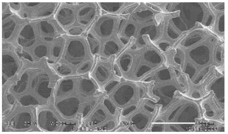
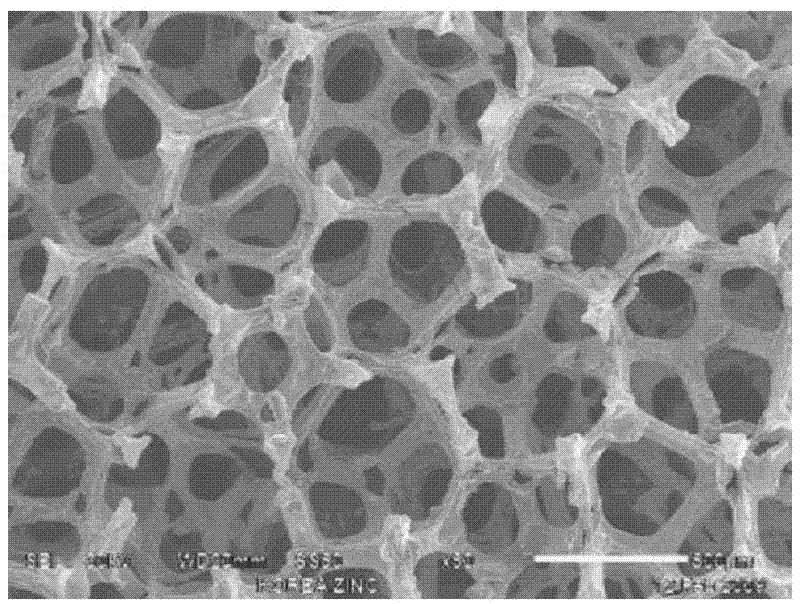
[0066] First, foamed polyurethane was used as a starting material for manufacturing iron foam. The thickness of the foamed polyurethane used was 1.7 mm, and the average diameter of the cells was 575 μm.
[0067] The prepared polyurethane foam is in the state of having undergone basic pretreatment. At this time, nickel-titanium (Ni-Ti) and copper-titanium (Cu-Ti) are deposited by the PVD device installed in the roll-to-roll equipment.
[0068] Therefore, the embodiments of the present invention will be described below in the order of nickel-titanium (Ni-Ti), copper-titanium (Cu-Ti).
[0069] 1. Example of depositing nickel-titanium (Ni-Ti)
Embodiment A1
[0071] Nickel was deposited first followed by titanium on the prepared polyurethane foam.
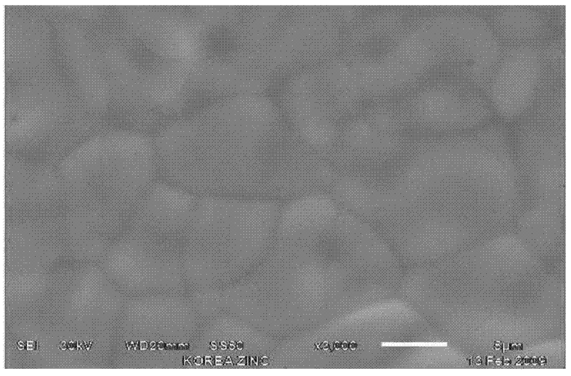
[0072] In Example A1, the deposition was carried out with a mixing ratio of nickel and titanium of 5:5, and the thickness of the deposited mixed layer of nickel and titanium was 0.17 μm.
[0073] The electroconductive porous body deposited with the above-mentioned nickel and titanium was subjected to iron plating in a plating tank having the composition shown in Table 1.
[0074] When electroplating iron, the electrolytic condition of the electroplating tank is that the current density of the apparent cathode is 700A / m 2 , the temperature and pH of the plating solution are shown in Table 1. The surface density of the electroplated conductive porous body is 420g / m 2 .
[0075] Spray and pickle the electroplated conductive porous body with a hydrochloric acid solution at 60° C. and a pH value of 1 to 1.5, and then spray air to remove the pickling solution. Thereafter, washing was perf...
Embodiment A2
[0081] In Example A2, the deposition was carried out with a mixing ratio of nickel and titanium of 7:3, and the thickness of the deposited mixed layer of nickel and titanium was 0.2 μm.
[0082] The electroconductive porous bodies described above were iron-plated in a plating tank having the composition shown in Table 1.
[0083] When electroplating iron, the electrolytic condition of the electroplating tank is that the current density of the apparent cathode is 500A / m 2 , the temperature and pH of the plating solution are shown in Table 1. The surface density of the electroplated conductive porous body is 418g / m 2 .
[0084] Spray and pickle the electroplated conductive porous body with a hydrochloric acid solution at 60° C. and a pH value of 1 to 1.5, and then spray air to remove the pickling solution. Thereafter, washing was performed by spraying water at 60° C., and water was removed by spraying air. Next, cleaning is performed by spraying 0.5-5 g / L antioxidant (water-so...
PUM
| Property | Measurement | Unit |
|---|---|---|
| Thickness | aaaaa | aaaaa |
| The average diameter | aaaaa | aaaaa |
| Surface density | aaaaa | aaaaa |
Abstract
Description
Claims
Application Information
 - R&D
- Intellectual Property
- Life Sciences
- Materials
- Tech Scout
- Unparalleled Data Quality
- Higher Quality Content
- 60% Fewer Hallucinations
Browse by: Latest US Patents, China's latest patents, Technical Efficacy Thesaurus, Application Domain, Technology Topic, Popular Technical Reports.
© 2025 PatSnap. All rights reserved.Legal|Privacy policy|Modern Slavery Act Transparency Statement|Sitemap|About US| Contact US: help@patsnap.com


