Distributed feedback laser array

A laser array and distributed feedback technology, which is applied to laser devices, semiconductor laser devices, optical resonator structures, etc., can solve the problems of lack of low-cost and high-reliability distributed feedback laser arrays, and achieve easy integration and fabrication, simplifying the process. , the effect of reducing costs

Inactive Publication Date: 2012-08-15
ZHEJIANG UNIV
View PDF8 Cites 16 Cited by
  • Summary
  • Abstract
  • Description
  • Claims
  • Application Information

AI Technical Summary

Problems solved by technology

Lack of low-cost and high-reliability dis...

Method used


Image

  • Distributed feedback laser array
  • Distributed feedback laser array
  • Distributed feedback laser array

Examples


Embodiment Construction

[0026] The present invention will be further described below in conjunction with accompanying drawings and examples.

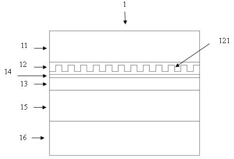
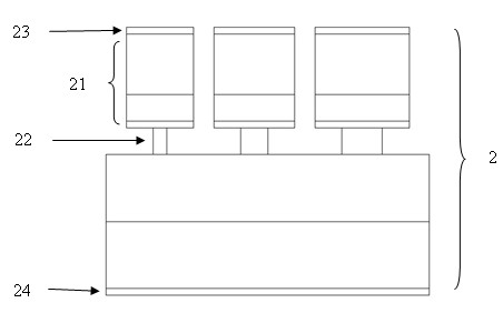
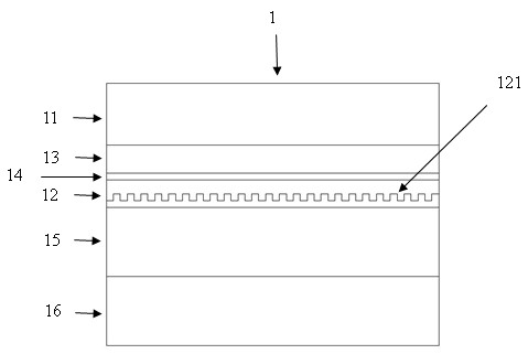
[0027] Such as figure 1 As shown, a distributed feedback laser array is composed of a plurality of distributed feedback lasers 2 arranged in parallel on the same semiconductor epitaxial wafer 1; the semiconductor epitaxial wafer 1 includes an upper cladding layer 11, an active layer from top to bottom 12. The spacer layer 14, the refractive index control layer 13, the lower cladding layer 15 and the substrate 16, the Bragg grating 121 for forming distributed feedback is arranged in the active layer 12 or the refractive index control layer 13; the period of the Bragg grating 121 is Keep consistent on the whole semiconductor epitaxial wafer 1 .

[0028] Such as figure 2 As shown, all the distributed feedback lasers 2 in a distributed feedback laser array are perpendicular to the Bragg grating 121; the upper cladding layer 11, the active layer 12 and the space...


PUM


Abstract

The invention discloses a distributed feedback laser array composed of distributed feedback lasers which are arranged in parallel and made on an epitaxial wafer of a same semiconductor. The epitaxial wafer of the semiconductor at least comprises an upper coating layer, an active layer, a spacing layer, a refractive index control layer, a lower coating layer and a substrate. The active layer or the refractive index control layer is internally provided with bragg gratings forming distributed feedback. All layers above the refractive index control layer form upper table-boards of the distributed feedback lasers. The refractive index control layer forms guided wave structures of the distributed feedback lasers, and the widths of the guided wave structures of all the distributed feedback lasers in the array are different. Any distributed feedback laser in the distributed feedback laser array is composed of an upper electrode, an upper table-board, a guided wave structure, a substrate and a lower electrode. Due to the adoption of the guided wave structures with different widths, each distributed feedback laser is provided with the bragg gratings with the same period, and meanwhile, the lasing wavelength has a certain excursion. The array can be used as a multi-wavelength laser and a tunable laser.

Description

technical field [0001] The invention relates to a distributed feedback laser array, in particular to a distributed feedback laser array with tunable lasing wavelength and multi-wavelength lasing. Background technique [0002] The popularization and development of information technology make the requirements for network technology higher and higher, especially for bandwidth. The development of next-generation technologies such as dense wavelength division multiplexing and passive optical networks has raised the need for multi-wavelength light sources. Although multiple discrete lasers can meet the wavelength requirements, the discrete devices are independent of each other, and the working conditions of each device are quite different, which leads to the inability to guarantee the overall performance of the light source equipment in terms of stability and reliability. In this context, tunable lasers have significant advantages. One type of tunable laser affects the parameter...

Claims


Application Information

Patent Timeline
IPC IPC(8): H01S5/40H01S5/12
Inventor 孟剑俊武林王磊何建军
Owner ZHEJIANG UNIV
Why Eureka
Try Eureka