Liquid distributor and vertical tube falling film evaporator comprising same

A falling-film evaporator and liquid distributor technology, applied in vertical tube evaporators, evaporator accessories, evaporation, etc., can solve the problem that the cylinder cannot move, and achieve the effect of reducing deposition and reducing the area

Active Publication Date: 2012-09-12
JIANGSU SUNPOWER TECH
View PDF7 Cites 20 Cited by
  • Summary
  • Abstract
  • Description
  • Claims
  • Application Information

AI Technical Summary

Problems solved by technology

During use, the sliding fit cylinder will adhere to the inner surface of the

Method used


Image

  • Liquid distributor and vertical tube falling film evaporator comprising same
  • Liquid distributor and vertical tube falling film evaporator comprising same
  • Liquid distributor and vertical tube falling film evaporator comprising same

Examples


Embodiment 1

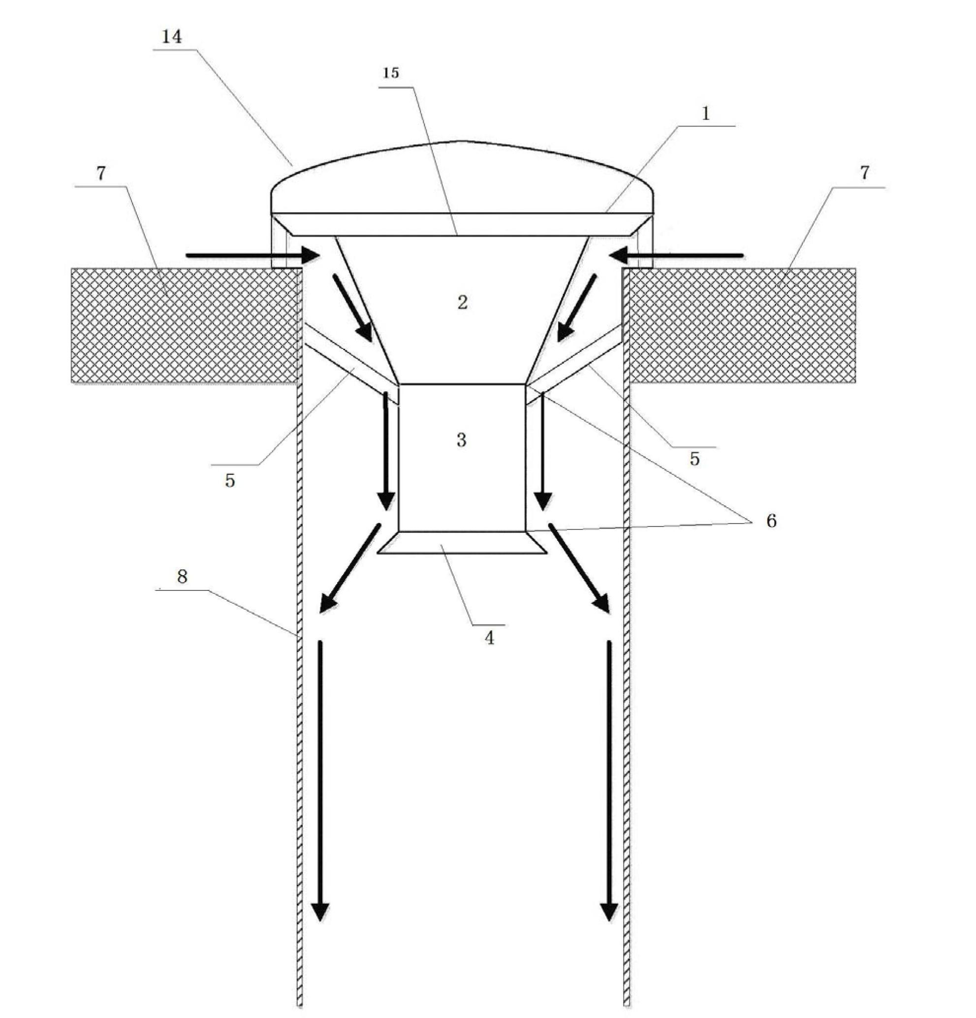
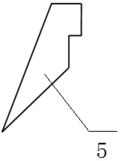
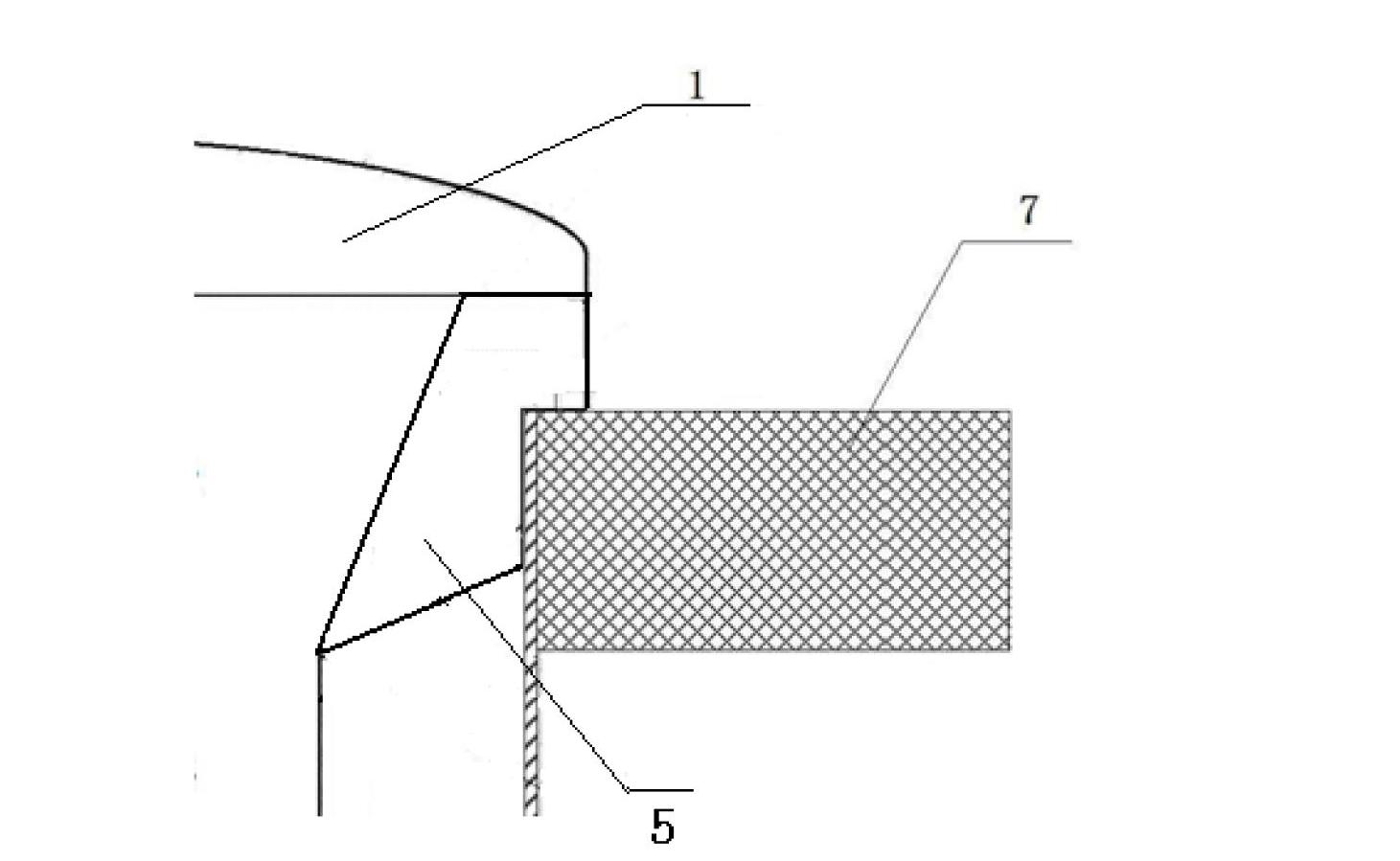
[0048] a kind of like figure 1 The liquid distributor 14 for the vertical tube falling film evaporator shown is mainly composed of a guide body 15 with a concave surface around the main body 6 and a bottom area of ​​the top cover 1 larger than the area of ​​the heat exchange tube 8 of the vertical tube falling film evaporator, and the The diversion body 15 is movably supported on the corresponding upper part of the heat exchange tube 8 of the vertical tube falling film evaporator, so that the edge of the bottom surface of the top cover 1 of the diversion body 15 and the upper surface of the tube sheet 7 of the vertical tube falling film evaporator are separated by a certain gap to form a gap. The support part 5 of the liquid channel is composed. The guide body 15 is symmetrically distributed along the central axis of the heat exchange tube of the vertical tube falling film evaporator, and consists of a main body 6 and a top cover 1 . The top cover 1 is cap-shaped, and its bot...

Embodiment 2

[0052] A sort of Figure 4 The shown liquid distributor 14 for the vertical tube falling film evaporator is mainly composed of a guide body 15 with a concave surface around it, and the guide body is movable supported and connected to the corresponding position in the upper part of the heat exchange tube 8 of the vertical tube falling film evaporator, and the guide body The upper surface of the fluid 15 is exposed to the support member 5 at the top of the heat exchange tube 8; the diameter of the upper surface of the guide body 15 is larger than the outer diameter of the heat exchange tube 8, so that the upper part of the concave surface of the guide body 15 (the part extending out of the heat pipe of the tube) ) edge and the top surface of the tube sheet 7 of the vertical tube falling film evaporator are separated by a certain gap to form a liquid inlet channel. The guide body 15 is symmetrically distributed along the central axis of the heat exchange tube 8 of the vertical tu...

Embodiment 3

[0056] a kind of like Figure 6 The liquid distributor 14 for the vertical tube falling film evaporator shown is mainly composed of a guide body 15 with a concave surface around the main body 6 and a bottom area of ​​the top cover 1 larger than the area of ​​the heat exchange tube 8 of the vertical tube falling film evaporator, and the The diversion body 15 is movably supported on the corresponding upper part of the heat exchange tube 8 of the vertical tube falling film evaporator, so that the edge of the bottom surface of the top cover 1 of the diversion body 15 and the upper surface of the tube sheet 7 of the vertical tube falling film evaporator are separated by a certain gap to form a gap. The support part 5 of the liquid channel is composed. The guide body 15 is symmetrically distributed along the central axis of the heat exchange tube 8 of the vertical tube falling film evaporator, and consists of a main body 6 and a top cover 1 . The top cover 1 is in the shape of a ha...


PUM


Abstract

The invention discloses a liquid distributor and a vertical tube falling film evaporator comprising the same. The liquid distributor mainly comprises a flow-guiding body and a support component, wherein the surrounding of a main body of the flow-guiding body is a concave surface, and the basal area of a top cover of the flow-guiding body is larger than the area of a tube mouth of a heat exchange tube of the vertical tube falling film evaporator; and the flow-guiding body is movably or fixedly supported in a corresponding position of the upper part in the heat exchange tube of the vertical tube falling film evaporator through the support component, so that a certain gap exists between the undersurface edge of the top cover of the flow-guiding body and the upper surface of a tube plate of the vertical tube falling film evaporator to form an intake channel. The vertical tube falling film evaporator comprises the liquid distributor. According to the structure of the flow-guiding body of the liquid distributor, on one hand, the area of a low-speed liquid area is reduced, therefore the deposition of suspended solids can be reduced; and on the other hand, the inner wall of the heat exchange tube forms smooth liquid flow with few bubbles and a uniform liquid film is easier to form.

Description

technical field [0001] The invention belongs to the technical field of heat exchange evaporation equipment, and relates to a liquid distributor and a vertical tube falling film evaporator containing the distributor. Background technique [0002] A vertical tube falling film evaporator utilizes a pump to circulate liquid from a low point to the top of a shell and tube heat exchanger. Once in the top, the liquid is distributed to the inner surface of one or more vertical tubes. Vertical tube falling film evaporator has the advantages of high heat transfer coefficient, short material heating time, small heat transfer temperature difference loss, energy saving, not easy to scale, easy to handle heat sensitive materials, etc., and is widely used in chemical industry, metallurgy, light industry, chemical fiber , food processing, medicine, seawater desalination, sewage treatment and other industrial sectors. In order to distribute the liquid evenly into each heating tube and form...

Claims


Application Information

Patent Timeline
IPC IPC(8): B01D1/30B01D1/22B01D1/06
Inventor D·J·彼得森D·K·卡尼纳伽马明刘丰李东
Owner JIANGSU SUNPOWER TECH
Why Eureka
Try Eureka