
Catalytic decomposition low-concentration hydrogen peroxide reactor, combustion chamber and application thereof

A hydrogen peroxide, catalytic decomposition technology, applied in the direction of chemical instruments and methods, chemical/physical processes, machines/engines, etc., can solve the problems of high price, insufficient safety, lower decomposition temperature and combustion temperature, etc., to achieve infinite Effects of heat dissipation loss, high safety, and increased life

Inactive Publication Date: 2012-09-12
葛明龙
View PDF5 Cites 26 Cited by
  • Summary
  • Abstract
  • Description
  • Claims
  • Application Information

AI Technical Summary

Problems solved by technology

[0008] In view of the disadvantages and deficiencies such as high price, insufficient safety, high freezing point, high decomposition temperature and combustion temperature, and single use of the existing technology of the catalytic decomposition hydrogen peroxide reactor and the combustion chamber, in order to make the catalytic decomposition hydrogen peroxide reactor And the use price of the combustion chamber is low, the safety is high, can be used all year round, the decomposition temperature and the combustion temperature are reduced more and the use is expanded. The present invention provides a novel catalytic decomposition hydrogen peroxide reactor and a catalytic decomposition hydrogen peroxide reactor. hydrogen peroxide combustion chamber

Method used


Image

  • Catalytic decomposition low-concentration hydrogen peroxide reactor, combustion chamber and application thereof
  • Catalytic decomposition low-concentration hydrogen peroxide reactor, combustion chamber and application thereof
  • Catalytic decomposition low-concentration hydrogen peroxide reactor, combustion chamber and application thereof

Examples


Embodiment Construction

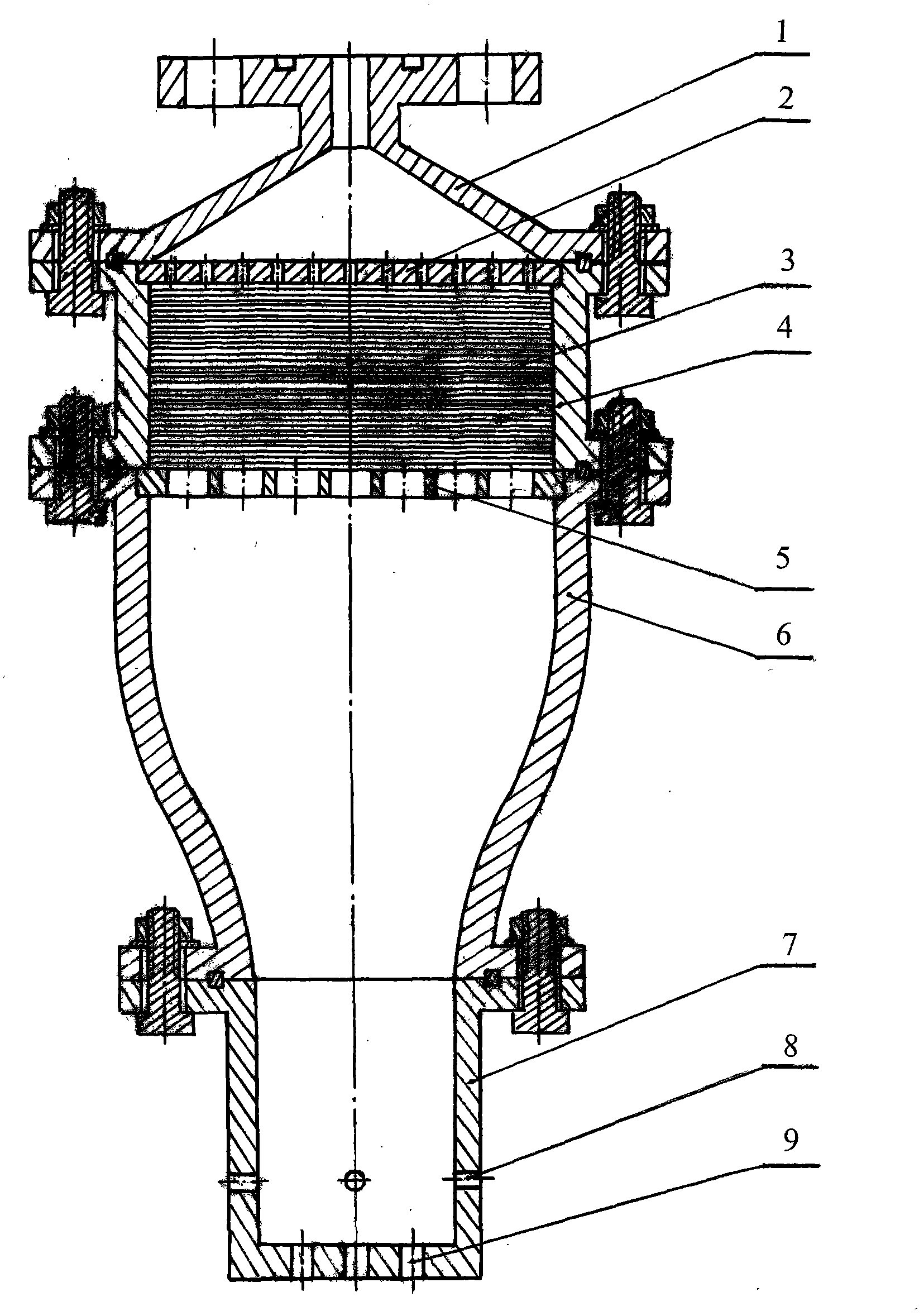
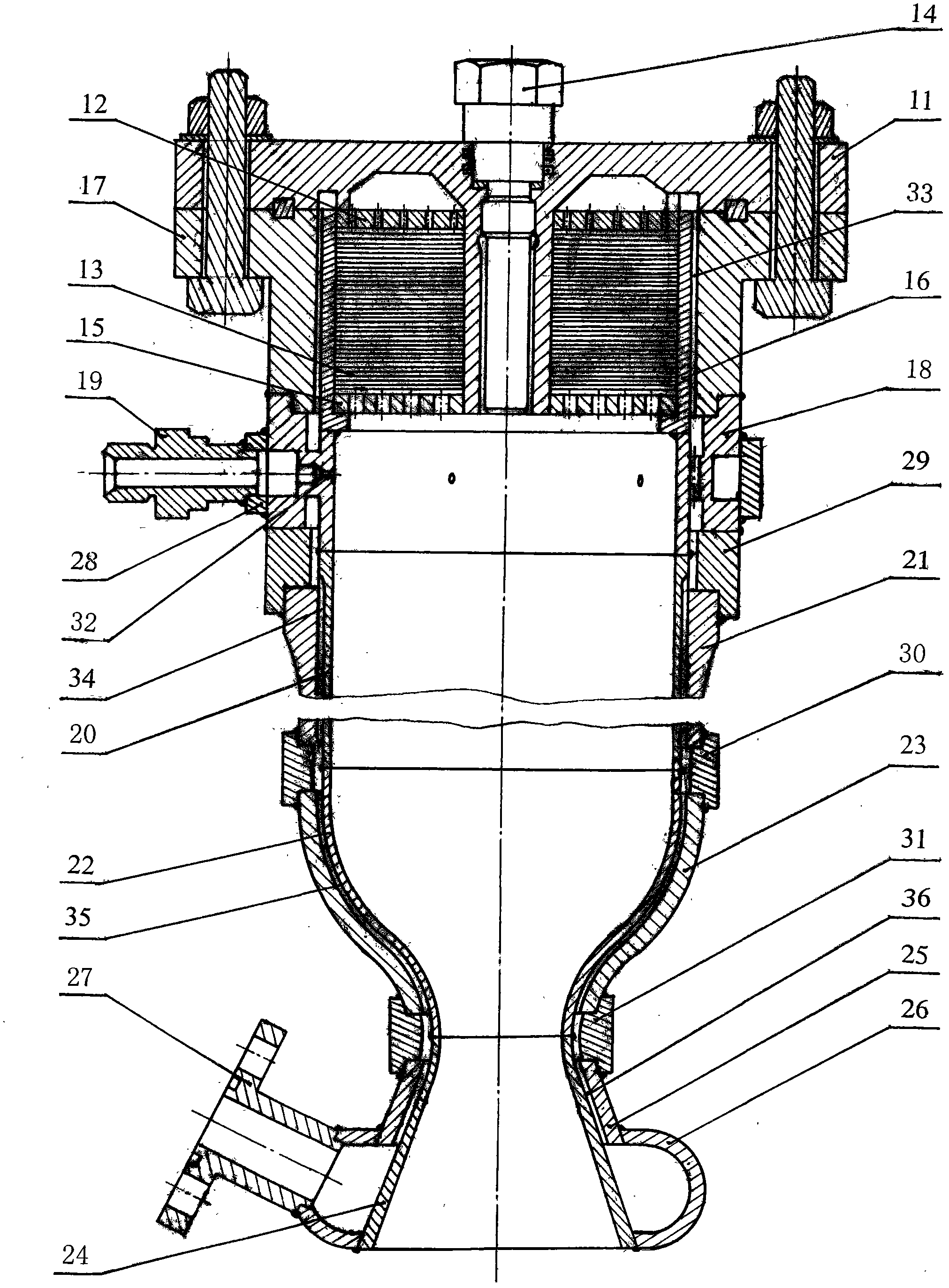
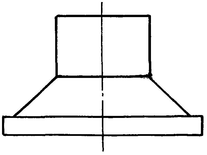
[0022] figure 1 , figure 2 and Figure 3-Figure 6 are three preferred embodiments of the present invention.

[0023] Such as figure 1 As shown, a catalytic decomposition hydrogen peroxide reactor of the present invention comprises a top cover 1, an equalizer plate 2, a catalytic bed 3, a decomposition chamber housing 4, a support plate 5, a collecting chamber housing 6 and a throat housing 7. Screw connection and limit fixation. The reactor adopts a multi-layered, low bed load and pre-contacted cylindrical pure silver mesh catalyst bed 3 for catalytically decomposing 40%-70% hydrogen peroxide, and the throat shell 7 is provided with radial holes 8 or / and shafts. To hole 9.

[0024] The radial holes 8 are a circle of circular holes evenly distributed along the circumference, which eject gas-liquid flow at the speed of sound, and are used for thermal oil recovery of downhole reactors.

[0025] Radial holes 8 are 1-5 circles of circular holes evenly distributed along the c...


PUM


Abstract

The invention relates to a catalytic decomposition low-concentration hydrogen peroxide reactor and a combustion chamber, which solve the problem that in the prior art, price is expensive, safety is not high, freezing point is high, decomposition temperature and ignition temperature are high, purpose is single and the like. A multilayer low-bed-load and pre-contact fine silver net catalysis bed for catalytic decomposition of 40%-70% of hydrogen peroxide is adopted, and service life is greatly prolonged. Radial holes or / and axial holes are arranged on a laryngeal casing of the catalytic decomposition low-concentration hydrogen peroxide reactor for using in underground reactor oil recovery by heating, mining and marine accident self rescuing and a life support system of spaceships and rocket oxidizer storage tank supercharging. The catalytic decomposition low-concentration hydrogen peroxide combustion chamber is provided with a plurality of radial spraying holes for spraying diesel oil or kerosene, an electronic spark plug for ignition, a combustion chamber body with the 40%-70% of hydrogen peroxide serving as a regeneration cooling agent and two kinds of spraying tubes, and the catalytic decomposition low-concentration hydrogen peroxide combustion chamber can be used for thrust chamber gas spraying thrust of a plurality of military projects and road ice and snow removal by heat and crude oil pollution.

Description

technical field [0001] The invention relates to a reactor for catalytically decomposing hydrogen peroxide and a combustion chamber for catalytically decomposing hydrogen peroxide based on the reactor. Background technique [0002] Catalytic decomposition hydrogen peroxide reactors and combustion chambers have been developed for more than 60 years, and the concentration of hydrogen peroxide has increased from 80% at the beginning to 90%-98% now. 90%-98% hydrogen peroxide, which is expensive and not safe enough, has a freezing point of -11.5°C-2.5°C, a catalytic decomposition temperature of 740°C-946°C, and a combustion temperature of 2450°C-2660°C when injected into kerosene. It is only used in aerospace The rocket motor drives the turbopump and thrust chamber jet propulsion. [0003] The existing thermal oil recovery technology is mainly water steam injection, which is effective and can be applied industrially. However, it is necessary to build a boiler steam station and a ...

Claims


Application Information

Patent Timeline
IPC IPC(8): B01J8/04F02K9/42
Inventor 葛明龙
Owner 葛明龙
Learn More