
Digital control gear milling machine of spiral bevel gear

A technology of spiral bevel gears and gear milling machines, which is applied to gear tooth manufacturing devices, gear cutting machines, belts/chains/gears, etc., and can solve the problems of loss of transmission accuracy and transmission efficiency, limitation of the movement speed of the tool spindle, and complicated clearance adjustment. , to achieve the effect of improving end-jumping accuracy, overcoming wear, and large transmission torque

Active Publication Date: 2015-04-22
通用技术集团天津第一机床有限公司
View PDF8 Cites 3 Cited by
  • Summary
  • Abstract
  • Description
  • Claims
  • Application Information

AI Technical Summary

Problems solved by technology

This will not only lead to the loss of transmission accuracy and transmission efficiency, but also the movement speed of the tool spindle will be limited; and only the intermittent indexing method can be used to process arc shrinking bevel gears and hypoid gears, and the continuous indexing method cannot be used Machining cycloidal contour bevel and hypoid gears
[0005] In the prior art, the transmission mode of the workpiece spindle box of the gear milling machine mainly adopts the gear transmission, the gear transmission speed is high, but the motion stability is poor, and the gap is too large, so the gear anti-backlash mechanism is needed to make up for the above shortcomings
The traditional gear backlash elimination is achieved by adjusting the pin holes and cylindrical pins on the two spur gears. Due to the long-term wear of the spur gears, the gap between them becomes larger and larger, and the cylindrical pins need to be repeatedly disassembled or re-drilled. , so the gap adjustment is cumbersome and inefficient

Method used


Image

  • Digital control gear milling machine of spiral bevel gear
  • Digital control gear milling machine of spiral bevel gear
  • Digital control gear milling machine of spiral bevel gear

Examples


Embodiment Construction

[0026] In order to further understand the invention content, characteristics and effects of the present invention, the following examples are given, and detailed descriptions are as follows in conjunction with the accompanying drawings:

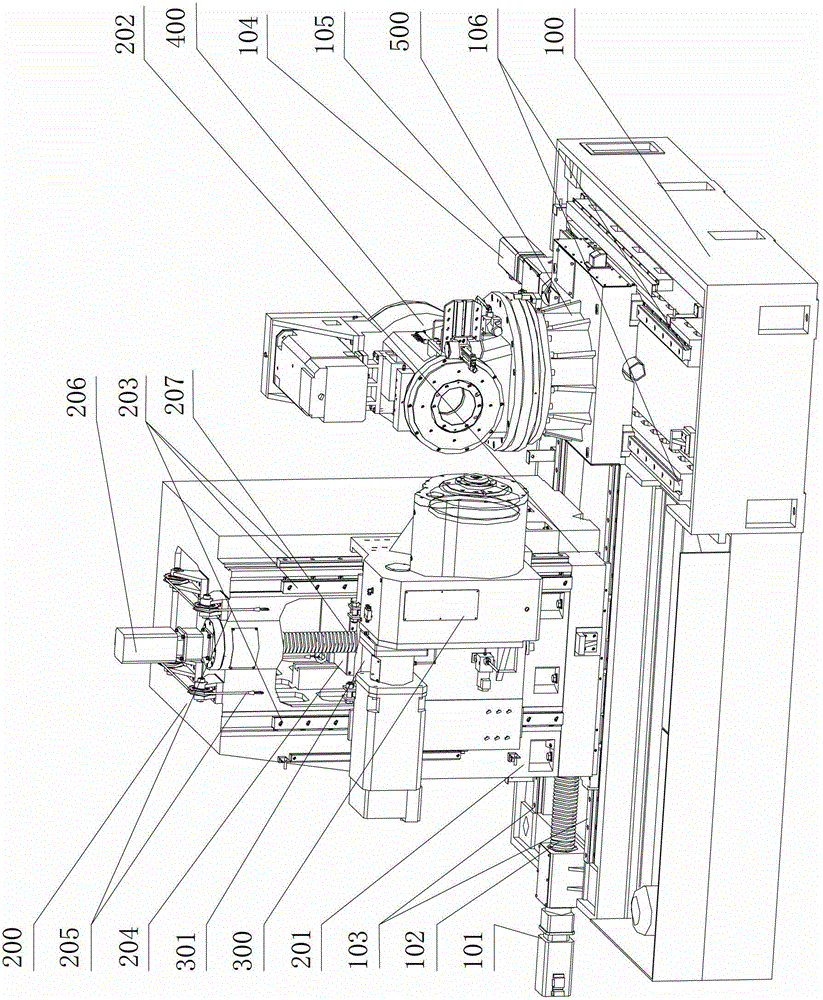
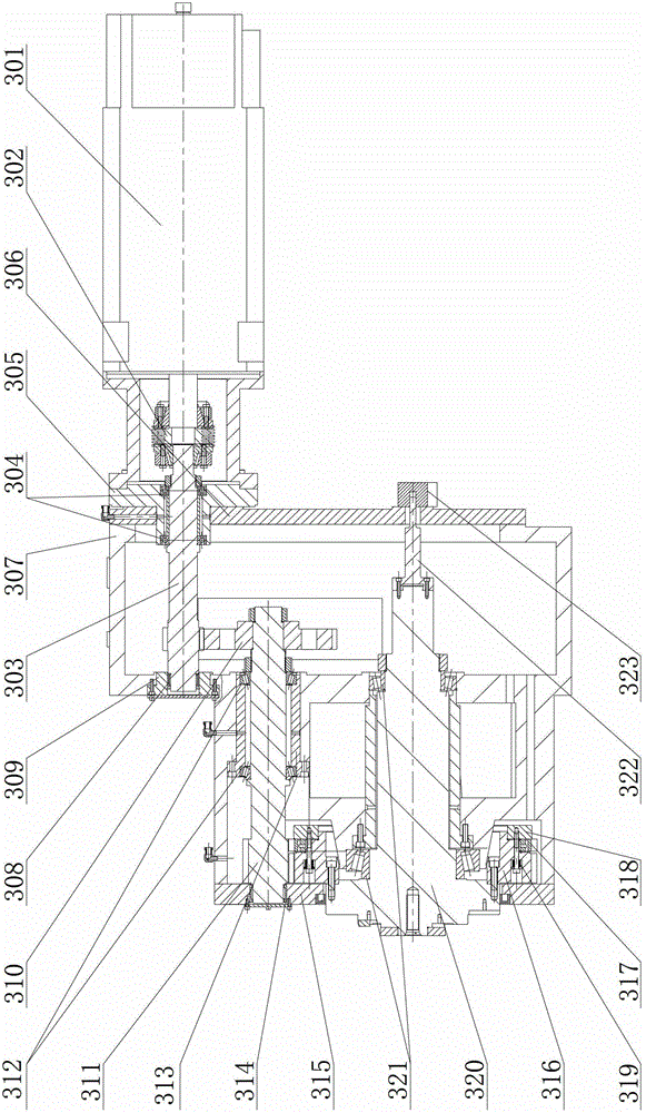
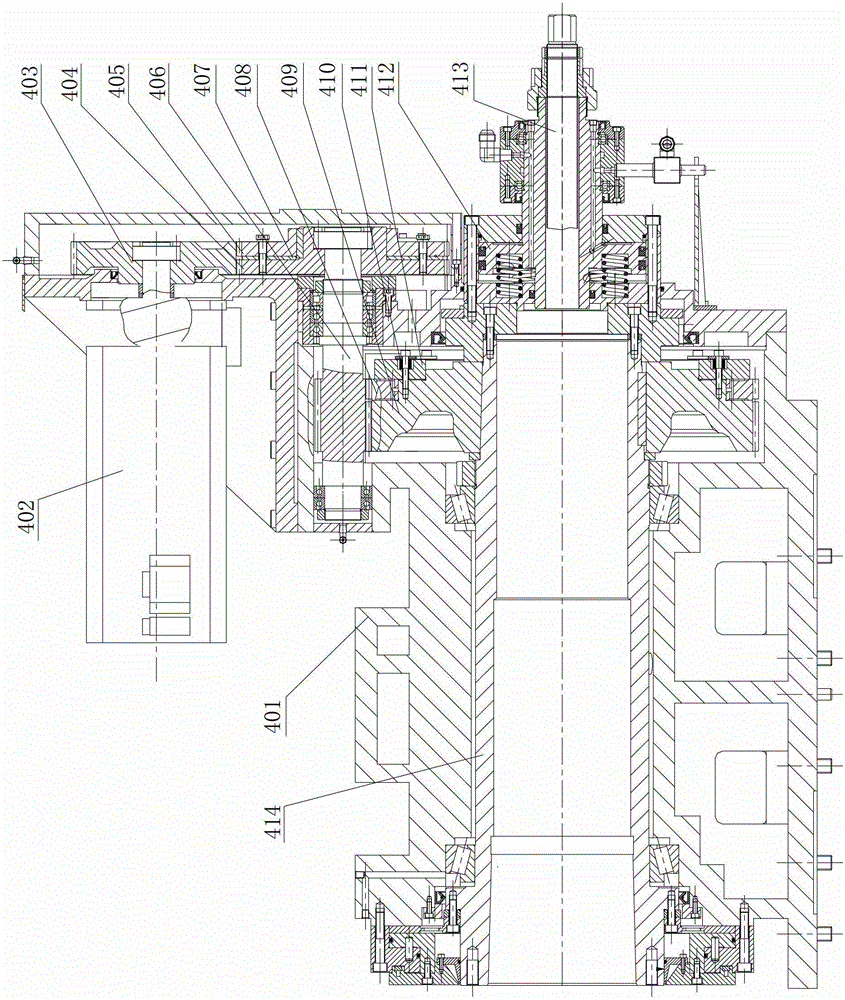
[0027] see Figure 1-Figure 4 , CNC spiral bevel gear grinding machine, including bed 100, column 200, tool headstock 300, workpiece headstock 400, rotary table 500, electrical system, pneumatic system and hydraulic system, the electrical system, pneumatic system and hydraulic Not shown in the system diagram. The rotary table is installed on the bed through the second linear guide rail 106, the workpiece spindle box 400 is installed on the rotary table, and the second ball screw 105 is driven by the second servo motor 104 to make the rotary table 500 move along the second linear guide rail 106. Move back and forth on the bed. A grinding wheel correction mechanism is installed on the workpiece headstock, the bed adopts an L-shaped structure ...


PUM


Abstract

The invention relates to a digital control gear milling machine of a spiral bevel gear. The digital control gear milling machine comprises a machine body, uprights, a cutter spindle housing, a workpiece spindle housing and a rotary working platform. The digital control gear milling machine is characterized in that the machine body is of an L-shaped structure with a slope on the surface, one side edge of the machine body, which is close to the outside, is provided with a chip groove, a hollow upper upright is arranged adjacent to the chip groove through a sliding plate, a wall-mounted sand wheel spindle housing is arranged on the outer wall of the upper upright, the upper upright is internally provided with a balance weight mechanism and is connected with the cutter spindle housing, a gear backlash eliminating mechanism is arranged on the workpiece spindle housing, and the rotary working platform adopts a rotary integer comprising a working platform spindle and the like and is of a fixed integral structure formed by a rotating platform bearing outer ring and a support sleeve. The digital control gear milling machine has the advantages that chips are smoothly discharged, deformation caused by overheating of the machine body is avoided, machining requirements of two gear mechanisms of a reducing gear and a constant-depth gear can be met, the rotary working platform is high in location precision and large in driving torque and has a self-locking function, the workpiece spindle box brings the convenience for regulation of a gap, and the problems of unstable gear transmission, overlarge gap, large noise and low efficiency are solved.

Description

technical field [0001] The invention belongs to the technical field of spiral bevel gear processing machine tools, in particular to a numerically controlled spiral bevel gear milling machine. Background technique [0002] The CNC spiral bevel gear milling machine is used for high-speed and precise milling of spiral bevel gears. Its purpose is to correct the deformation of the gear heat treatment, improve the precision and smoothness of the tooth surface, and meet the requirements of stable transmission, lower noise and higher precision. In the known technology, the chip removal structure of the gear milling machine body adopts an internal chip removal mechanism. Since the chip removal channel is long, it is not easy to dissipate the heat of iron chips. [0003] The CNC rotary table is the core component of the gear milling machine. The movement accuracy, bearing capacity, and ability to deal with impacts of the CNC rotary table are related to the production and processing ca...

Claims


Application Information

Patent Timeline
Patent Type & Authority Patents(China)
IPC IPC(8): B23F9/08B23F23/00B23Q5/10B23Q5/56B23Q1/26
Inventor 王秀梅王景召沈凤美刘福聪吴文仲齐百基胡光曦吴杰王威刘新瑞
Owner 通用技术集团天津第一机床有限公司
Learn More