

Structure of electrostatic dedusting device
A technology of electrostatic dust removal and dust collection device, which is applied in the direction of electrode structure, electrostatic separation, electrostatic effect separation, etc. It can solve problems such as difficult to have both, difficult to apply volume scheme, and dust collection plate spacing limitation, so as to achieve improved resistance and easy cleaning And maintenance, to avoid the effect of arc sparking
- Summary
- Abstract
- Description
- Claims
- Application Information
AI Technical Summary
Problems solved by technology
Method used
Image

Examples
Embodiment 1
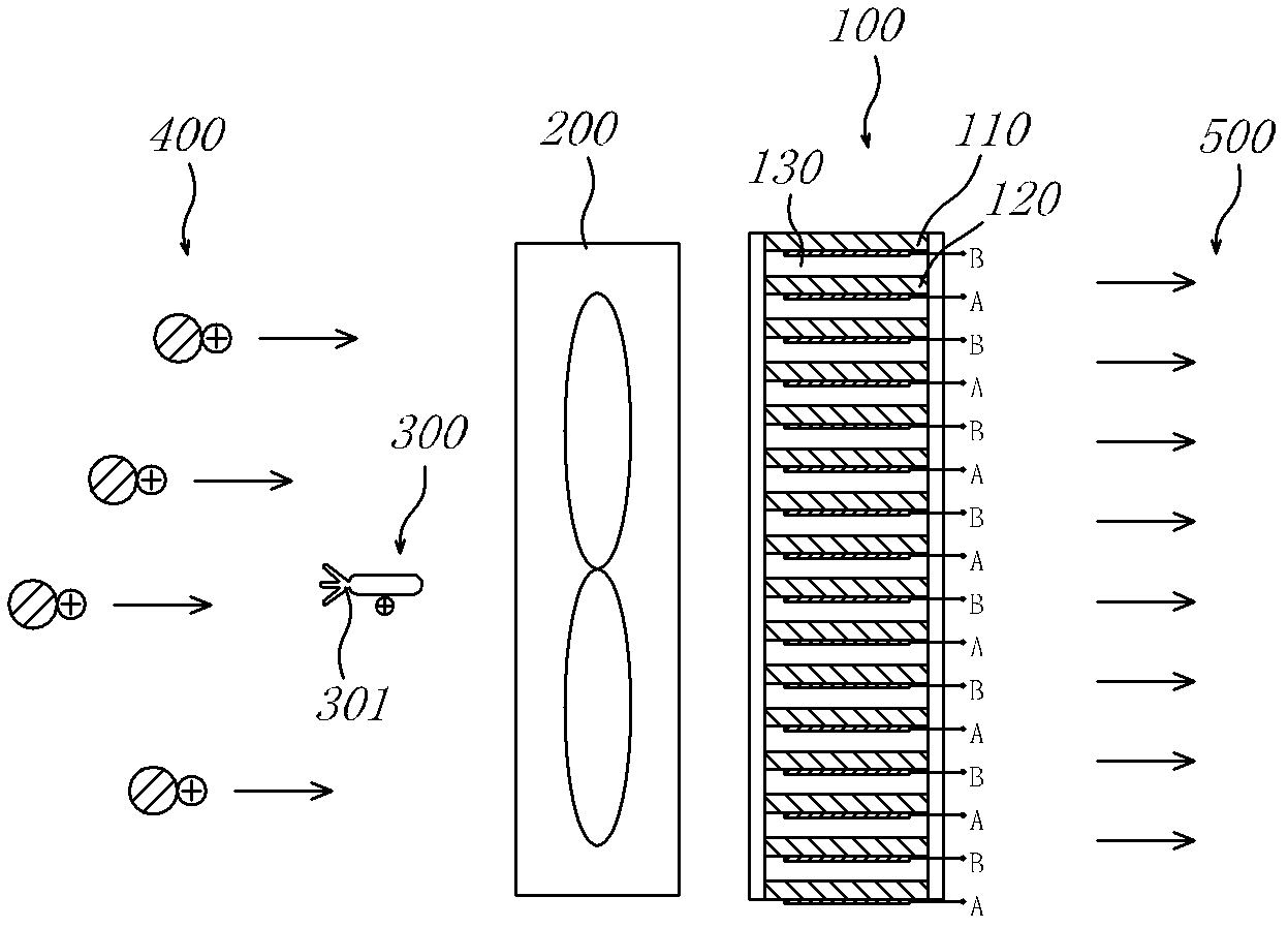
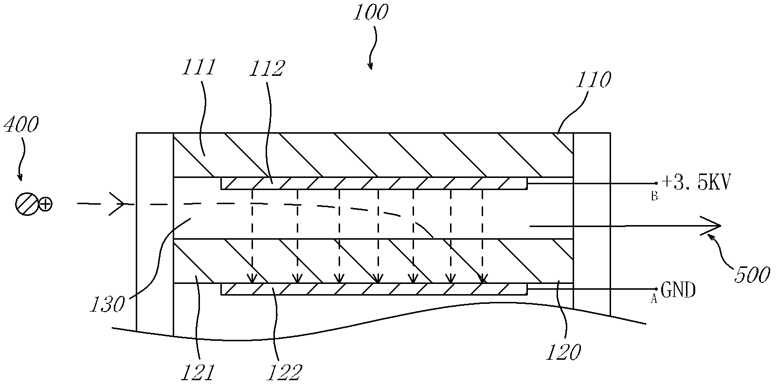
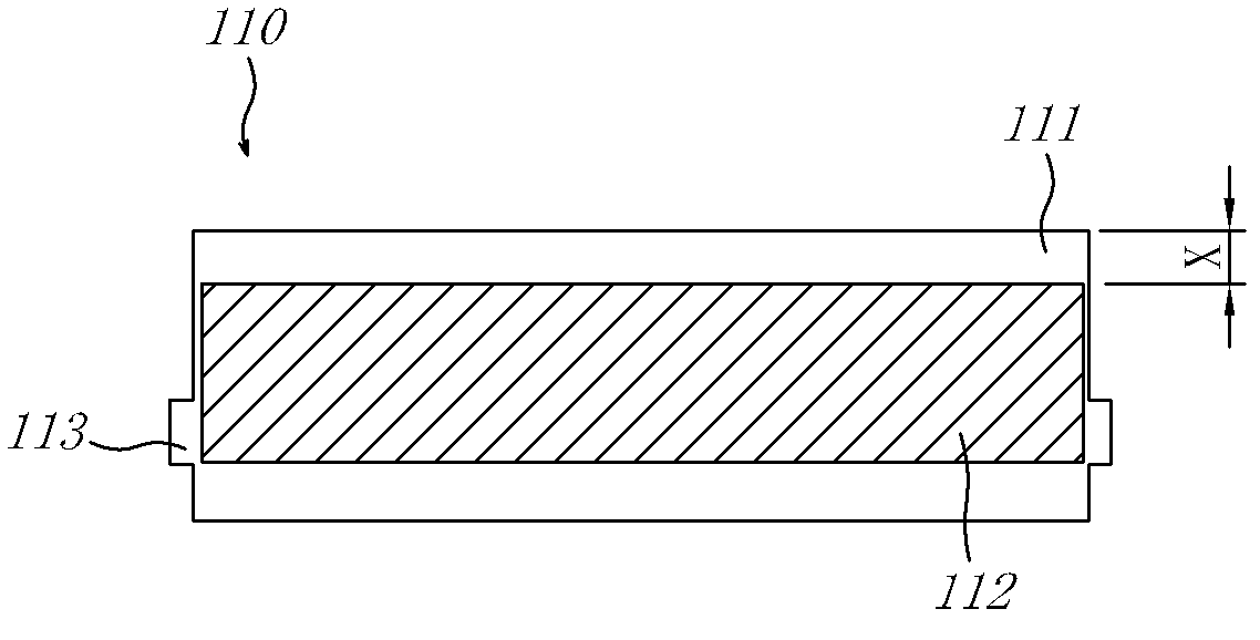
[0035] Such as figure 1 It is a schematic diagram of a side view of an embodiment of the present invention; figure 2 yes figure 1 Schematic illustration of the working principle of the illustrated embodiment, with details of the dust collection plate; image 3 yes figure 1 The bottom view of the dust collecting plate of the embodiment.
[0036] The dust collecting device 100 has dust collecting plates distributed in an array at intervals; for the convenience of description, the parts from the top to the first dust collecting plate 110 and the second dust collecting plate 120 will be described. The adjacent first dust collecting plate 110 and the second dust collecting plate 120 have a unidirectional electric field between each other, and a first dust removing air duct 130 crossing the electric field;
[0037] There is a fan device 200 on the front air flow path of the dust collecting device 100, which makes the air to be dedusted form a unidirectional controllable air flo...
Embodiment 2
[0042] Such as Figure 4 It is the bottom view of the dust collection plate of embodiment two; the overall structure of embodiment two is similar to embodiment one, the difference is that it is the dust collection plate at first, for the convenience of comparison, the first dust collection plate 110 of embodiment two is also taken out Compare. With image 3 Compared with the first dust-collecting plate 110 of the first embodiment shown, the first dust-collecting plate of the second embodiment has a larger empty section X, while the relative area of the first conductive plate 112 is smaller, and the present embodiment The first dust collecting plate 110 is a printed circuit board made of CEM1. The processing of the first dust-collecting plate 110 of this structure is very easy, whether it is the processing of the shape or the etching of the first conductive electrode plate 112 in the form of the copper-clad surface, it can be realized with a very mature process at a relativ...
Embodiment 3
[0045] Such as Figure 5 , is a schematic side view of the third embodiment; the dust collecting device 100, the blower device 200 and the high-voltage emitting head 301 in this embodiment are all the same as in the first embodiment; The negative pressure makes the air to be dedusted together with the charged particles 400 firstly sucked into the dust collecting device 100 , and then output as clean air 500 through the fan device 200 . This solution is suitable for occasions with a lot of dust, and can better protect the life of the fan device 200 .
PUM
 Abstract
Description
Claims
Application Information