Packaging device and packaging method

A packaging device and packaging method technology, applied in glass molding, glass manufacturing equipment, electrical components, etc., can solve the problems of inconvenient adjustment of pressing force, increase of operation time, and inability to obtain pressing effect, etc., to achieve ample material adaptability , Excellent technical effect, good material adaptability

Inactive Publication Date: 2012-09-26
SHANGHAI MICRO ELECTRONICS EQUIP (GRP) CO LTD
View PDF8 Cites 13 Cited by
  • Summary
  • Abstract
  • Description
  • Claims
  • Application Information

AI Technical Summary

Problems solved by technology

However, in the current encapsulation process of OLED laser glass powder, as pointed out in US2010 / 0118912, there may be some defects when coating glass paste on the encapsulation cover glass substrate, such as bumps, voids and thickness differences, which may cause Final Product Package Failure
Due to the existence of these defects, the yield of laser packaging is low
Therefore, US2010 / 0130091 proposes to compress the upper and lower glass substrates by vacuum pressing and sealing the glass body, so that the glass frit can be as close as possible to the glass substrate and reduce the impact of the gap. The compression effect, especially when the packaging glass is pre-packaged as described in US2007 / 0267972; while US2009 / 0233514 proposes to use mechanical compression to keep the glass frit as close as possible to the glass substrate and reduce the impact of the gap, but it needs Move the corresponding mechanical pressing device before laser scanning, increasing the operation time, and the pressing force is inconvenient to adjust

Method used


Image

  • Packaging device and packaging method
  • Packaging device and packaging method
  • Packaging device and packaging method

Examples


Embodiment Construction

[0036] Specific embodiments of the present invention will be described in detail below in conjunction with the accompanying drawings.

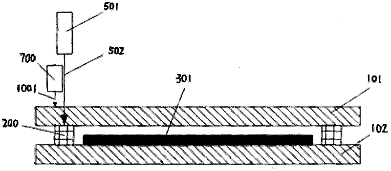
[0037] figure 1 It is a structural schematic diagram of the packaging device involved in the present invention. figure 1 Although not shown in , it should be understood that the sealed glass package to be scanned by a laser or other radiation source is placed on a flat wafer stage and its position can be kept measurable during the packaging process. Such as figure 1 As shown in , a laser or other radiation source system 501 is used to generate a radiation beam 502, which passes through the package cover glass 101 and irradiates on the package line glass frit 200, and the scanning movement of the radiation spot along the package line is formed by relative displacement. However, the jetting fluid jetting assembly 700 of the present invention is independent of the radiation source system 501, and jets the fluid 1001 to the packaging line and ne...


PUM


Abstract

The invention provides a packaging device which comprises a stage, a radiation source and a fluid source. The stage is used for bearing a packaging structure for assembly, wherein the packaging structure is provided with a first substrate, a second substrate, and a molten material which is arranged between the first substrate and the second substrate to form at least one cavity; the radiation source is used for heating the molten material so that the molten material combines with the connecting surface of the first substrate and the second substrate and the cavity forms a hermetic packaging structure; and the fluid source provides a fluid beam, wherein the fluid beam acts on the first substrate and is used for pressing the a molten material between the first substrate and the second substrate.

Description

technical field [0001] The invention relates to the field of manufacturing technology of flat panel displays, in particular to a controllable injection fluid compaction system and a method for completing laser glass frit packaging by using the system. Background technique [0002] Flat Panel Display (FPD) has developed rapidly since the 1990s, and gradually matures, and is widely used in household appliances, computers and communication products. There are two types of flat panel displays: active light emitting and passive light emitting. The former refers to display devices that display the medium itself to emit light and provide visible radiation, including plasma display (PDP), vacuum fluorescent display (VFD), field emission display (FED), electroluminescent display (LED) and organic light-emitting diode display (OLED) Wait. The latter means that it does not emit light itself, but uses the optical characteristics of the display medium to change after being modulated by...

Claims


Application Information

Patent Timeline
Patent Type & Authority Applications(China)
IPC IPC(8): C03B23/24H01L51/56H01L51/52
CPCY02P40/57
Inventor 韦学志陈勇辉
Owner SHANGHAI MICRO ELECTRONICS EQUIP (GRP) CO LTD
Why Eureka
Try Eureka