Purifying system for multi-phase photocatalysis treatment of waste gases

A waste gas purification system and purification system technology, which is applied in the direction of chemical instruments and methods, separation methods, and separation of dispersed particles, to achieve the effects of expanding the scope of application, benefiting environmental protection, and improving the purification rate

Inactive Publication Date: 2012-10-10
CHONGQING UNIV
View PDF5 Cites 11 Cited by
  • Summary
  • Abstract
  • Description
  • Claims
  • Application Information

AI Technical Summary

Problems solved by technology

[0004] The purpose of the present invention is to provide a purification system for heterogeneous photocatalytic treatment of exhaust gas in view of the shortcomings of the existing titanium dioxide photocatalytic degradation treatment exhaust gas purification system

Method used


Image

  • Purifying system for multi-phase photocatalysis treatment of waste gases
  • Purifying system for multi-phase photocatalysis treatment of waste gases
  • Purifying system for multi-phase photocatalysis treatment of waste gases

Examples


Embodiment 1

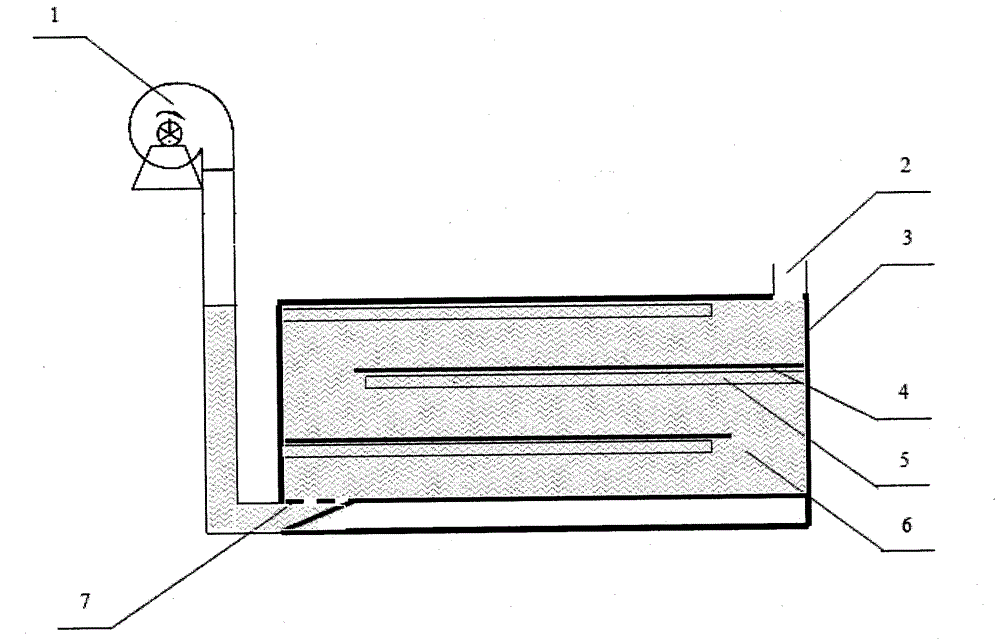
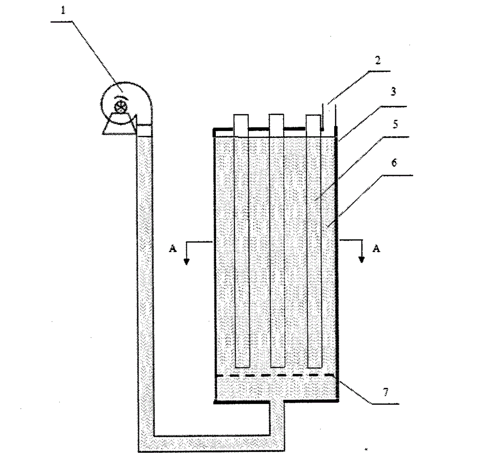
[0031] Such as figure 1 As shown, a purification system for heterogeneous photocatalytic treatment of waste gas is a filling type waste gas treatment and purification system. The filling type multiphase photocatalytic treatment of waste gas purification system mainly includes a blower 1, an exhaust port 2, and a reaction chamber 3. Ultraviolet lamp tube 5, nano-titanium dioxide suspension 6, exhaust gas diffuser 7, etc.

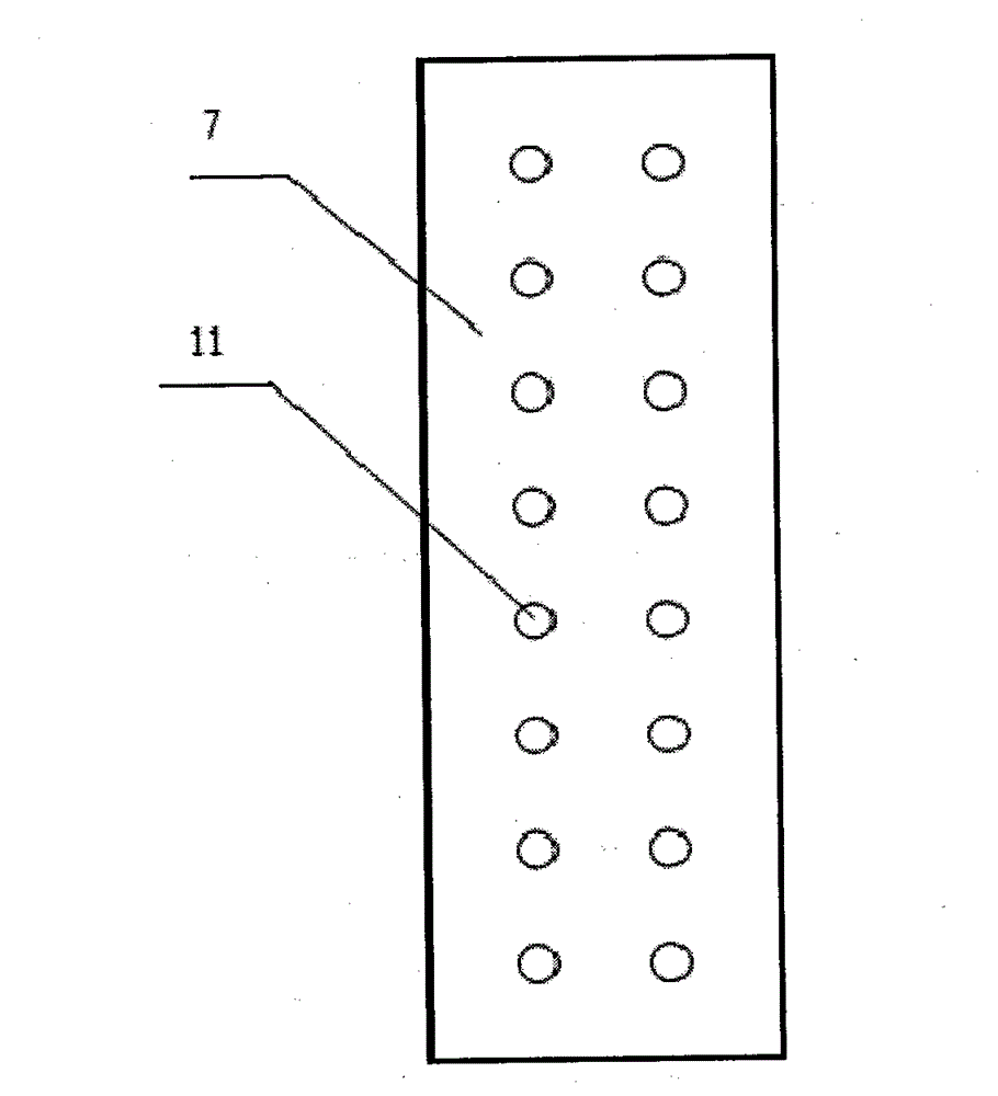
[0032] The blower 1 is a commercially available component, the outlet of the blower 1 communicates with the gas inlet at the bottom of the reaction chamber 3, and the waste gas to be treated passes through the blower 1 and the connecting pipe, and flows from the air inlet After passing through the exhaust gas disperser 7 and dispersing, it enters the reaction chamber 3 for treatment and purification.

[0033] The material of the reaction chamber 3 is stainless steel, and the shape of the reaction chamber 3 is rectangular. The rectangular reaction chamber 3 ...

Embodiment 2

[0037] A purification system for heterogeneous photocatalytic treatment of waste gas, same as Example 1, wherein:

[0038] The rectangular reaction chamber 3 has a length of 1000 mm, a width of 440 mm, a height of 600 mm, and a wall thickness of 1 mm. At the bottom of the rectangular reaction chamber 3 located on the side of the blower 1, a circular through hole (namely an air inlet) with a diameter of 60 mm is provided. In the rectangular reaction chamber 3, perpendicular to the upper side of the air inlet, the gas-guiding baffles 4 with a pitch of 100 mm are fixed horizontally and staggeredly, and the length of each air-guiding baffle 4 is 700mm, the width is matched with the width of the rectangular reaction chamber 3, the thickness is 1mm, and the material is a stainless steel plate. The lower surface of 4 is respectively fixed with the above-mentioned array of ultraviolet lamp tubes 5 parallel to each other with a distance of 50mm, and the power of each ultraviolet lamp ...

Embodiment 3

[0042] A purification system for heterogeneous photocatalytic treatment of waste gas, same as Example 1, wherein:

[0043] The rectangular reaction chamber 3 has a length of 2000mm, a width of 1800mm, a height of 2000mm, and a wall thickness of 3mm. At the bottom of the rectangular reaction chamber 3 on one side of the blower 1, a circular through hole (ie, an air inlet) with a diameter of 250 mm is provided. In the rectangular reaction chamber 3, perpendicular to the top of the air inlet, the air guide baffles 4 with a spacing of 300 mm are fixed horizontally and staggeredly, and the length of each air guide baffle 4 is It is 1850mm, the width matches the width of the inner chamber of the rectangular reaction chamber 3, the thickness is 3mm, and the material is a stainless steel plate. The lower surface of 4 is respectively fixed with the above-mentioned array of ultraviolet lamp tubes 5 parallel to each other with a distance of 100mm, and the power of each ultraviolet lamp ...


PUM


Abstract

A purifying system for multi-phase photocatalysis treatment of waste gases relates to a purifying system for titanium dioxide photocatalysis degradation treatment of the waste gases. The purifying system can be a filling type waste gas purifying system and a spraying type waste gas purifying system and mainly comprises a blower, a waste gas disperser, a reaction chamber, an ultraviolet light tube, a nano titanium dioxide suspension and the like. The purifying system provided by the invention has the advantages as follows: the structure is simple, the use is flexible and convenient, various organic waste gases or reducing waste gases can be treated, and suitability for treatment of various industrial waste gases is achieved; the waste gas treatment is complete, the purifying rate is high, the secondary pollution problem is avoided, and environmental protection is facilitated; and the applicability is high, and the popularization and the application are convenient. The purifying system provided by the invention can be extensively applied to treatment of various industrial waste gases in large, medium-size and small-sized factories and is an ideal purifying system for gas-liquid-solid multi-phase photocatalysis treatment of the waste gases.

Description

technical field [0001] The invention belongs to the technical field of exhaust gas treatment, and in particular relates to a purification system for treating exhaust gas by photocatalytic degradation of titanium dioxide. Background technique [0002] With the rapid development of science and technology, the industrial manufacturing industry is becoming more and more powerful. While benefiting mankind, a large amount of waste gas will be generated, and its components are usually volatile organic gases such as aldehydes, organic amines, and benzene series. The environmental pollution caused by these waste gas emissions has caused serious harm to the ecological environment and human health, so it has become the focus of attention. As far as the current industrial level is concerned, the discharge of these gas pollutants cannot be completely avoided, so people urgently need to develop an efficient, environmentally friendly and simple waste gas treatment system. [0003] Existin...

Claims


Application Information

Patent Timeline
Patent Type & Authority Applications(China)
IPC IPC(8): B01D53/90B01D53/78
Inventor 季金苟谢袁菲闫政清郭静楚莎莎于凯石朝辉徐溢
Owner CHONGQING UNIV
Why Eureka
Try Eureka