Wind power spindle flange upsetting process

A wind power spindle and wind power flange technology, which is applied in the field of wind power spindle flange upsetting technology, can solve problems such as uneven deformation and the like

Active Publication Date: 2012-10-17
JIANGSU JINYUAN FORGE
View PDF8 Cites 17 Cited by
  • Summary
  • Abstract
  • Description
  • Claims
  • Application Information

AI Technical Summary

Problems solved by technology

At present, the upsetting of the wind power flange at the shaft end of the large wind power main shaft is carried out by the traditional forging method, which will lead to the problem of uneven deformation during upsetting

Method used


Image

  • Wind power spindle flange upsetting process
  • Wind power spindle flange upsetting process

Examples


Embodiment

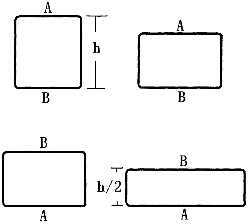
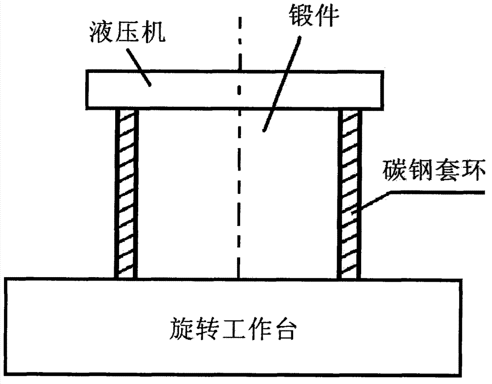
[0015] The upsetting process of the wind power flange of the present invention comprises the following steps:

[0016] Firstly, the billet used for the flange of the wind power main shaft according to the present invention is prepared in a steelmaking furnace. Raise the temperature to 1300°C in the steelmaking furnace, add steelmaking raw materials to refine it into a low-alloy high-strength steel billet for wind power flanges, and the chemical composition of the low-alloy high-strength steel is: carbon: 0.25-0.60wt%, silicon: 0.35~0.50wt%, manganese: 1.2~1.70wt%, phosphorus: 0.015~0.025wt%, sulfur: 0.012~0.02wt%, chromium: 0.30~0.80wt%, molybdenum: 0.10~0.30, vanadium: 0.15~0.30wt% %, nickel: 0.30-0.50wt%, copper: 0.15-0.3wt%, nitrogen: 0.015-0.05wt%, titanium: ≤0.2wt%, niobium: ≤0.06wt%, and the balance is iron; then the low Alloy high-strength steel blanks are continuously cast into Φ1500mm blanks, which are forged to obtain forgings for wind power flanges;

[0017] Then,...


PUM


Abstract

The invention discloses a wind power spindle flange upsetting process, which comprises the following steps of: performing a first upsetting sate by a rotating local upsetting process, and by combining an overturning process; and arranging a loop on the excircle of the forging and continuing to perform a second upsetting stage process. When the process is used, forging cost and labor intensity are reduced, and the nonuniformity of deformation is relieved.

Description

technical field [0001] The invention relates to the technical field of wind power generators, in particular to an upsetting process for a wind power main shaft flange. Background technique [0002] In today's society, with the increasingly serious problems of global energy shortage and environmental pollution, the search for renewable energy has become a major issue faced by countries all over the world. Compared with other energy sources, natural wind energy not only has a large amount of reserves, is widely distributed, and will never be exhausted, but also has the advantages of fast start-up, short construction period, less basic investment than hydropower station construction, strong flexibility, and can effectively curb the greenhouse effect and Sandstorm disasters, green environmental protection and other characteristics, so wind power has increasingly become the focus of research. [0003] Wind power tower flanges (hereinafter referred to as wind power flanges) are k...

Claims


Application Information

Patent Timeline
Patent Type & Authority Applications(China)
IPC IPC(8): B21J5/08C22C38/46
Inventor 葛艳明杨志华袁志伟殷定保
Owner JIANGSU JINYUAN FORGE
Why Eureka
Try Eureka