Pulse plasma drilling machine system

A pulsed plasma and drilling rig technology, which is applied to drilling equipment, earth-moving drilling, drilling equipment and methods, etc., can solve the problems that the drilling rig cannot work normally, the position of the working coil is sensitive, and it is difficult to meet such requirements, etc. Achieve the effect of improving energy utilization efficiency and increasing depth

Inactive Publication Date: 2012-10-17
ZHEJIANG UNIV
View PDF6 Cites 14 Cited by
  • Summary
  • Abstract
  • Description
  • Claims
  • Application Information

AI Technical Summary

Problems solved by technology

The structure of downhole equipment designed with this structure is relatively simple, and the drilling process is simple, but there is a problem: after rock breakdown, the characteristic impedance is less than 1 ohm (Scott J. MacGregor et al, Plasma Channel Miniature Hole Drilling Technology[J], IEEE Transactions on plasma science, 2004: 2055-2061), assuming that the characteristic impedance of the transmission line is Z, after the rock breaks down, a plasma channel is formed inside, and the characteristic impedance of the plasma in the channel is R, then the energy efficiency obtained on the load for:
The characteristic impedance of the existing pulse transmission cables (RG215, RG218, etc.) is generally 50 ohms or even higher, and the minimum characteristic impedance of the coaxial water cable for the pulse plasma drilling rig system developed by Qingdao Ocean Research Institute in China is 10 ohms, it is difficult to achieve high energy efficiency with load rocks at such a high characteristic impedance as a transmission line
In response to this situation, many research institutions have proposed new circuit structures to solve this impedance matching problem. J Biela et al. proposed a solid-state switching power supply (J. Biela et al, Solid State Modulator for Plasma Channel Drilling[J], IEEE Transactions on plasma science,2009: 1093-1099), this method is sensitive to the position of the working coil, and it is difficult to meet this requirement in actual work
Professor Yan Keping of Zhejiang University developed a combined pulse power supply based on pulse forming network (ZL 2009 2 0295616.0). This method can better achieve impedance matching, but there are still problems in solving long-distance pulse transmission
[0008] In addition, as the length of the pulse transmission cable increases, the steepness of the pulse front will further decrease due to the influence of stray inductance or stray capacitance. When the rising front of the voltage does not meet the requirements of hundreds of nanoseconds, the drilling machine cannot It works, which is one of the reasons why conventional plasma drills are not capable of deep drilling

Method used


Image

  • Pulse plasma drilling machine system
  • Pulse plasma drilling machine system
  • Pulse plasma drilling machine system

Examples


specific Embodiment approach

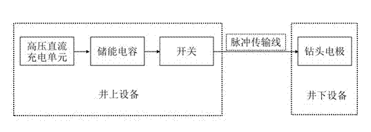
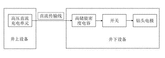
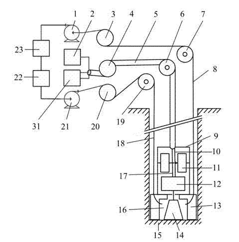
[0040] Such as figure 2 As shown, the circuit part of the pulse plasma drilling machine system of the present invention mainly includes a high voltage DC charging unit, a high energy storage density capacitor and a switch. Different from the traditional pulse plasma drilling rig system: the present invention places the high-voltage DC charging unit on the well, while the high energy storage density capacitor 11, the switch 12 and the drill bit electrodes are placed down the well. The uphole equipment (high-voltage DC charging unit) and downhole equipment (high energy storage density capacitor 11, switch 12 and drill bit electrodes) in the circuit part are connected together through a DC transmission line. see Figure 4 , as a specific implementation of the present invention, the three-phase alternating current is boosted by the transformer T and then rectified by the rectifier bridge to become a high-voltage direct current. This part is the high-voltage direct current chargi...


PUM


Abstract

The invention discloses a pulse plasma drilling machine system. The pulse plasma drilling machine system comprises a trigger signal generating device, a high-voltage direct-current charging unit, a photoelectric composite transmission cable, a first winch, a first fixed pulley, a high-voltage pulse forming unit, a deionized water circulation unit and a drill electrode. An aboveground device and an underground device in a circuit part are connected together through a direct-current transmission line, high-voltage pulse generated by the high-voltage pulse forming unit can be directly loaded on the drill electrode, the using of a long-distance pulse transmission line is avoided, the problem of mismatching between the impedance of the pulse transmission line and the characteristic impedance of a passageway after a rock is punctured does not exist, and thus the energy utilization efficiency and the drilling depth are greatly increased.

Description

technical field [0001] The invention belongs to the technical field of oil and gas exploration and development, and relates to a separate pulse plasma drilling rig system. Background technique [0002] With the rapid increase in demand for oil and gas resources, the development of advanced drilling equipment is an urgent need for our oil and gas strategy. Traditional drilling methods include mechanical drilling and chemical blasting. The former utilizes the impact and shear action of mechanical drilling tools on rocks to break rocks. It has the characteristics of simple structure and convenient operation, but has the disadvantages of easy wear and tear of drilling tools; It has the advantages of simple operation and fast blasting speed by causing impact to achieve rock crushing, but at the same time it has disadvantages such as large crushing disturbance, generation of toxic and harmful substances, and irregular hole patterns. [0003] Facing the growing demand for drillin...

Claims


Application Information

Patent Timeline
Patent Type & Authority Applications(China)
IPC IPC(8): E21B7/00
Inventor 章志成闫克平黄逸凡裴彦良
Owner ZHEJIANG UNIV
Why Eureka
Try Eureka