
Solar catalytic oxidation-membrane separation three-phase fluidized bed circulation reaction device

A three-phase fluidized bed, photocatalytic reaction technology, applied in the field of solar photocatalytic oxidation-membrane separation three-phase fluidized bed circulating reaction device, can solve the problems of large catalyst influence, catalyst poisoning, small Reynolds number, etc. The effect of large wastewater treatment capacity, convenient operation and maintenance, and simple structure

Inactive Publication Date: 2012-10-24
TIANJIN POLYTECHNIC UNIV
View PDF0 Cites 11 Cited by
  • Summary
  • Abstract
  • Description
  • Claims
  • Application Information

AI Technical Summary

Problems solved by technology

However, due to the low flow rate of this type of reactor, the Reynolds number is small, and the fluid is in a laminar flow state, there are mass transfer limitations
At the same time, the reactor is operated in a non-closed manner, and the catalyst is greatly affected by the surrounding environment, which may easily cause catalyst poisoning
[0010] (2) Suspension-type photocatalytic reactor: The efficiency of the suspension-type photocatalytic reactor is higher than that of the fixed type, and its advantage is that the fluid is in a turbulent state without mass transfer restrictions; at the same time, the reactor is in a closed state and there is no volatile pollution In addition, the structure of the reactor is simple and the investment cost is low; but it has the problem of separation, recovery and reuse of the catalyst, so how to realize the recycling of the catalyst is the main problem faced by the suspension photocatalytic reactor

Method used


Image

  • Solar catalytic oxidation-membrane separation three-phase fluidized bed circulation reaction device
  • Solar catalytic oxidation-membrane separation three-phase fluidized bed circulation reaction device
  • Solar catalytic oxidation-membrane separation three-phase fluidized bed circulation reaction device

Examples


Embodiment Construction

[0028] The present invention will be described in detail below in conjunction with the accompanying drawings and specific implementation.

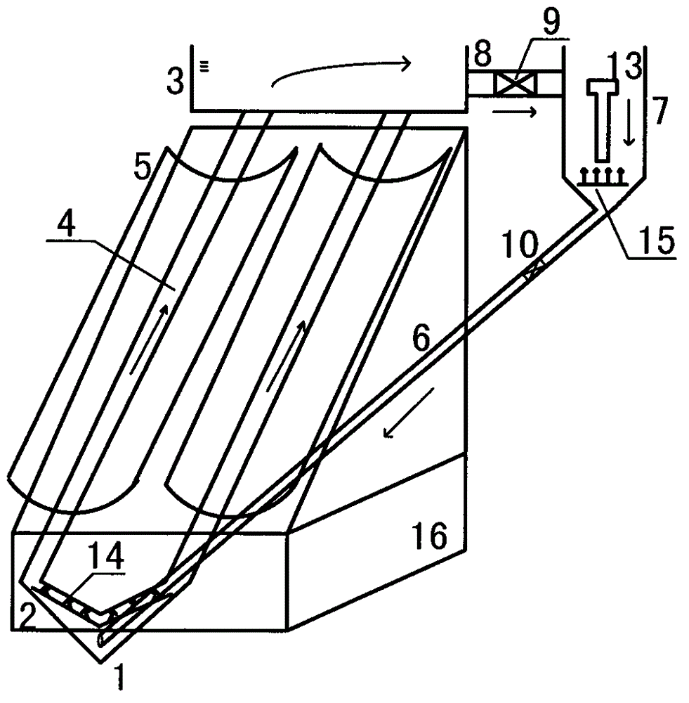
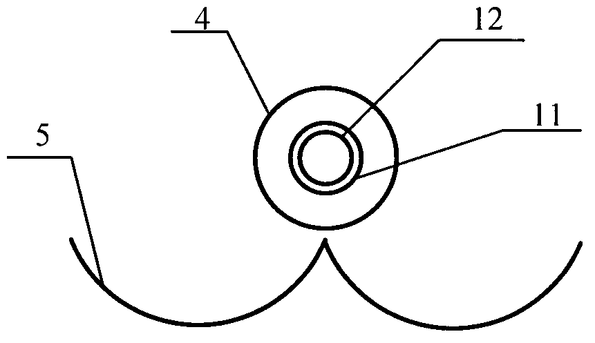
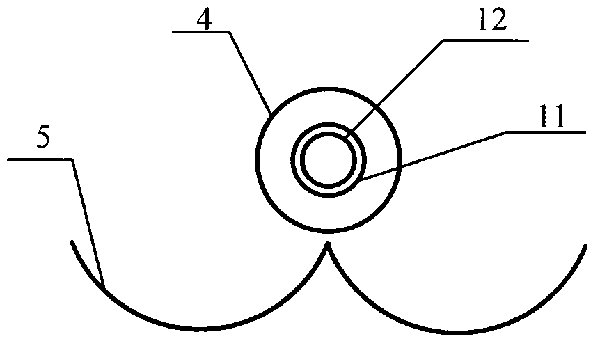
[0029]As shown in the accompanying drawings, the solar photocatalytic oxidation-membrane separation three-phase fluidized bed circulation reaction device of the present invention includes a photocatalytic reaction zone and a membrane separation zone, and the photocatalytic reaction zone includes a lower water tank 2 and an upper water tank 3 , compound parabolic daylighting plate 5 and tubular reactor, described tubular reactor is arranged on the central position of compound parabolic daylighting plate 5, wherein Fig. 2 (a) is solar photocatalytic oxidation-membrane separation three-phase fluidized bed circulation The cross-sectional view of the tubular reactor structure when the device is a dual light source structure, including high silica glass outer tube 4 and built-in quartz tube or quartz cold trap tube 11 and other quartz cooling tub...


PUM


Abstract

The invention relates to the structural characteristics and working principle of a novel solar catalytic oxidation-membrane separation three-phase fluidized bed circulation reaction device. The solar catalytic oxidation-membrane separation three-phase fluidized bed circulation reaction device comprises a photocatalytic oxidation reaction region consisting of a composite paraboloid lighting board, a tubular reactor, an upper part water tank, a lower part water tank and the like and a membrane separation region consisting of a membrane separator shell and an immersed membrane component. The working principle is as follows: under the action of an aeration flow, waste water and a catalyst are rapidly mixed to form a gas, liquid and solid three-phase fluidized bed reaction system and internal circulation flow of waste water, the lower part water tank, the tubular reactor, the upper part water tank, a communicating tube, a membrane separator, a circulating tube and the lower part water tank; photocatalytic degradation reaction is carried out when the waste water flows through the tubular reactor; TiO2 in the membrane separator shell is intercepted by the membrane component, and treated water is discharged from a water outlet; and the intercepted TiO2 returns to the lower part water tank and the tubular reactor through the circulating tube along with internal circulation flow of the waste water, so that the TiO2 is circulated and repeatedly utilized in the reaction device.

Description

technical field [0001] The invention relates to a reaction device, in particular to a solar photocatalytic oxidation wastewater treatment device not affected by the weather: a solar photocatalytic oxidation-membrane separation three-phase fluidized bed circulation reaction device, which can be applied to toxic The pretreatment or advanced treatment of harmful and refractory organic wastewater can also be applied to the advanced treatment of slightly polluted drinking water. Background technique [0002] With the rapid development of my country's social economy, a large amount of waste pollutants are inevitably produced, which leads to serious environmental pollution and ecological damage. Traditional treatment methods cannot completely eliminate degradation pollutants, and are likely to cause secondary pollution, with narrow application range and high energy consumption. In recent years, the use of photocatalytic oxidation technology to degrade pollutants has received wides...

Claims


Application Information

Patent Timeline
IPC IPC(8): C02F1/72C02F1/30C02F1/44
CPCY02W10/37
Inventor 解立平邹晨曦王俊
Owner TIANJIN POLYTECHNIC UNIV
Learn More