Processing apparatus for drying sludge by utilizing waste heat of draught fan and method for using the same

A technology for drying sludge and treatment equipment, which is applied in dehydration/drying/thickened sludge treatment, energy wastewater treatment, etc., and can solve problems such as large floor area, difficulty in ventilation and odor, and strong influence from sunlight and weather , to achieve the effect of high safety and energy saving

Active Publication Date: 2012-10-24
上海仁创环境科技有限公司
View PDF4 Cites 12 Cited by
  • Summary
  • Abstract
  • Description
  • Claims
  • Application Information

AI Technical Summary

Problems solved by technology

[0005] The purpose of the present invention is to provide a treatment device and method for drying sludge using the waste heat of a fan, so as to solve the existing problems in

Method used


Image

  • Processing apparatus for drying sludge by utilizing waste heat of draught fan and method for using the same
  • Processing apparatus for drying sludge by utilizing waste heat of draught fan and method for using the same
  • Processing apparatus for drying sludge by utilizing waste heat of draught fan and method for using the same

Examples


Embodiment 1

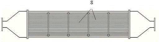
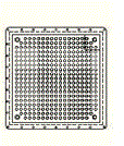
[0032] Figure 1-Figure 4 Schematically shows the structure of a preferred embodiment of the present invention, as shown in the figure, this preferred embodiment includes a solar greenhouse, a sludge pressure conveying system, a sludge drying system, an exhaust gas waste heat circulation system, and the sludge pressure conveying The system is placed in a solar greenhouse. The sludge pressure conveying system includes a screw pump (or plunger pump), a mud distributor and a belt conveyor. The solar greenhouse is connected to the exhaust gas waste heat circulation system. The waste gas waste heat circulation system includes Humidity-adjusted air intake device, aeration blower, filter, special heat exchanger, the sludge drying system is placed in the solar greenhouse, including screw pump (or plunger pump), mud distributor, sewage Mud turning and throwing machine, waste heat floor heating system, waste heat circulating air heating system, heat exchanger and temperature controller,...

Embodiment 2

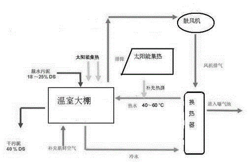
[0034] In embodiment 2, other structures are all the same as embodiment 1, and the difference is: the processing device is also provided with an auxiliary energy source, the solar greenhouse is connected to the auxiliary energy source, and the auxiliary energy source is a solar thermal collector or a heat pump system, It is activated when the weather is bad or the fan fails.

Embodiment 3

[0036] In Example 3, other structures are the same as those in Example 2, except that the aeration blower is connected to a heat exchanger, and one end of the heat exchanger is connected to a water pipe to transfer heat to water for heating the sludge. Connect the filter, after the exhaust gas is treated, it will be compressed by the aeration blower and heated up, and then the heat will be exchanged through the heat exchanger, and then discharged into the aeration tank.


PUM


Abstract

The invention discloses a processing apparatus for drying sludge by utilizing waste heat of a draught fan and a method for using the same. The processing apparatus comprises a solar energy greenhouse, a sludge pressure delivery system, a sludge drying system, an exhaust gas circulation system. The sludge pressure delivery system that is arranged inside the solar energy greenhouse includes a screw pump or a plunger pump, a sludge arrangement machine and a belt conveyor. The exhaust gas circulation system that is connected with the solar energy greenhouse includes an inlet device, an aeration blower, a heat exchanger and a filter, wherein the inlet device is used for adjusting the air input according to the temperature and the humidity. The sludge drying system that is arranged inside the solar energy greenhouse includes a screw pump or a plunger pump, a sludge arrangement machine, a sludge turning-throw device, a aeration blower waste heat heating system, a heat exchanger and a temperature controller. And the aeration blower is used for waster heat recovery as well as gas circulation and ventilation. According to the invention, during the sludge processing process, the energy can be effectively saved and the power consumption can be reduced, so that energy conservation and emission reduction can be realized in a real sense.

Description

[0001] technical field [0002] The invention relates to a device and method for treating sludge, in particular to a complete set of treatment device and method for drying sludge by utilizing waste heat of an aeration blower in a sewage treatment plant. [0003] Background technique [0004] With the continuous improvement of people's quality of life, the requirements for urban sewage treatment have also increased accordingly, and the load of urban treatment plants has increased day by day. Sludge is a product of sewage treatment. The sludge produced by urban sewage treatment contains a large amount of organic matter, which can be used as agricultural fertilizer, but it also contains a large number of harmful components such as bacteria, parasite eggs, and heavy metal ions brought from production sewage. , need to do sludge reduction, stabilization, and harmless treatment. The main methods of treatment are drying treatment (concentration, dehydration, etc.) and stabilizatio...

Claims


Application Information

Patent Timeline
IPC IPC(8): C02F11/12
CPCY02W10/37
Inventor 石文政
Owner 上海仁创环境科技有限公司
Why Eureka
Try Eureka