Laser drilling method for miniature loudspeaker brackets

A speaker bracket and laser drilling technology, which is applied in laser welding equipment, welding equipment, metal processing, etc., can solve the problems of high tolerance and precision requirements, to ensure stability and consistency, reduce processing costs, and save labor hours Effect

Inactive Publication Date: 2012-10-31
刘天镐
View PDF6 Cites 4 Cited by
  • Summary
  • Abstract
  • Description
  • Claims
  • Application Information

AI Technical Summary

Problems solved by technology

However, because the aperture of Φ0.15mm is too small, and the tolerance accuracy of plus or minus 0.005mm is also very high, the injection molding process (plastic bracket) or stamping process (hardware brac

Method used


Image

  • Laser drilling method for miniature loudspeaker brackets
  • Laser drilling method for miniature loudspeaker brackets
  • Laser drilling method for miniature loudspeaker brackets

Examples


Embodiment 1

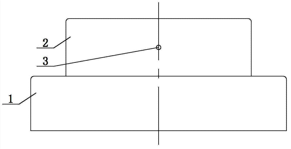
[0035] see Figure 1~3 As shown, a laser drilling method for a miniature horn bracket, the horn bracket is transferred to the laser drilling machine by the vibrating plate through automatic feeding. The laser drilling machine uses a sensor to detect whether the horn bracket is sent to the station. When the sensor detects that the feeder sends the bracket to the laser drilling station, the laser drilling machine is triggered to work, otherwise the laser drilling machine does not work.

[0036] Specifically in this embodiment, the horn bracket has an open first end 1 and a sealed second end 2, and a laser drilling machine punches a round hole 3 on the side wall of the second end 2 of the horn bracket.

Embodiment 2

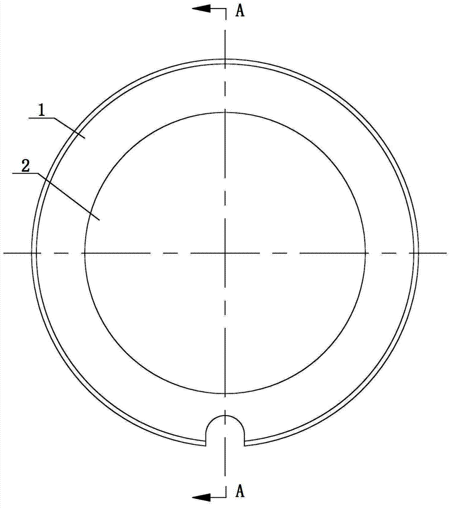
[0038] The difference from Embodiment 1 is only that the laser drilling machine drills holes on the speaker bracket, and the rest are the same. see Figure 4 As shown, the horn bracket has an open first end 1 and a sealed second end 2, and a laser drilling machine punches a circular hole 3 on the sealed end surface of the second end 2 of the horn bracket.

Embodiment 3

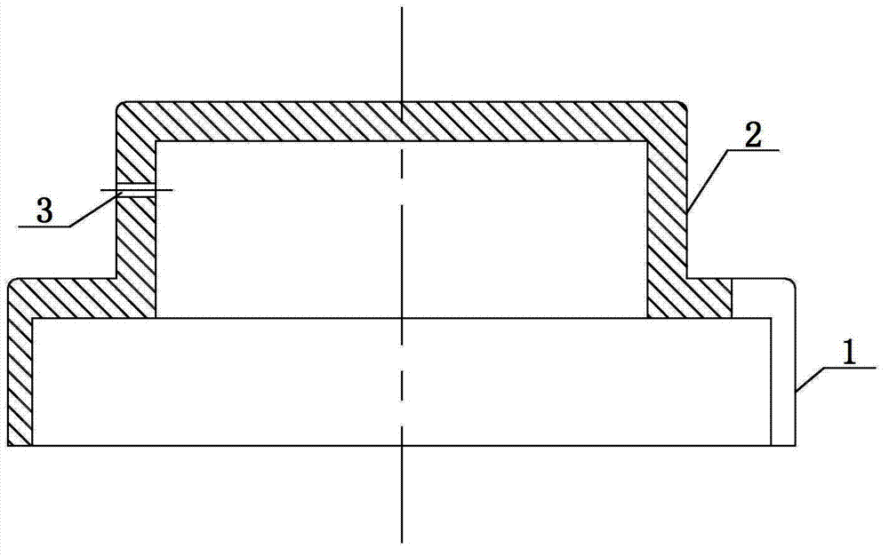
[0040] The difference from the above two embodiments is only that the laser drilling machine punches holes on the speaker bracket, and the rest are the same. see Figure 5 As shown, the horn bracket has an open first end 1 and a sealed second end 2, and a laser drilling machine punches a round hole 3 on the end surface where the first end 1 and the second end 2 of the horn bracket are in contact.

[0041] In the present invention, the vibrating plate transfers the horn bracket to the laser punching machine through an automatic feeding method. When the sensor of the laser punching machine detects that the feeder sends the horn bracket to the laser drilling station, the laser punching machine is triggered to work. Use the laser to drill the specified micro-holes in the designed position of the speaker bracket. Due to the creative use of the laser drilling machine and the automatic feeding machine, it replaces the original adjustment of the speaker by manually coating the glue an...


PUM


Abstract

The invention discloses a laser drilling method for miniature loudspeaker brackets. The method is characterized in that through drilling holes on a miniature loudspeaker bracket by using laser, the required basic unit air flow quantity of a loudspeaker vibrating plate in the process of vibrating is adjusted, and then the tone quality is regulated. According to the invention, through creatively using the cooperation of a laser drilling machine and an automatic feeding machine, micropores are drilled on a miniature loudspeaker bracket, so that compared with the traditional loudspeaker bracket drilling process which is implemented through using mechanical processing or die forming, so that the pore diameter is overlarge, and then manually coating glue for adhering damping materials so as to adjust the sound effect of a loudspeaker, the method disclosed by the invention can be used for reducing the application of raw materials such as loudspeaker glue and damping materials, reducing the processing process, and saving the artificial time; and under the condition of guaranteeing the accuracy of drilling through a laser drilling machine, an effect of batch production is achieved, the production efficiency is obviously improved, and the stability and consistency of frequency response characteristics and tone quality performances of a loudspeaker are ensured, thereby significantly reducing the processing cost of the loudspeaker.

Description

technical field [0001] The invention relates to a drilling process for a miniature horn bracket, in particular to a laser drilling method for an earphone horn bracket. Background technique [0002] Micro horn brackets refer to horn brackets with a size range of 3mm to 75mm, and their shapes include: round, oval, special-shaped, and square. The existing production processes for micro horn brackets are mainly injection molding (plastic brackets) and stamping processes. (hardware bracket), but no matter which of the above processes is used, a single hole or multiple holes need to be opened on the flange or bottom of the speaker bracket to adjust the air flow required during the vibration of the speaker diaphragm, and then to adjust the sound quality . For example, if Figure 6-9 As shown, the traditional miniature hardware round speaker bracket (also known as: iron shell, iron basin, basin frame) includes an open first end 101 and a sealed second end 102. In order to adjust th...

Claims


Application Information

Patent Timeline
IPC IPC(8): B26F1/31B26D7/06B23K26/36B23K26/42B23K26/382B23K26/70
Inventor 刘天镐
Owner 刘天镐
Why Eureka
Try Eureka