Waste heat recovering efficient gas stove

A waste heat recovery and gas stove technology, which is applied in the field of gas stoves, can solve the problems that the stove cannot be turned off (using an open flame or keeping a kindling, not supporting full combustion of gas, and large heat loss of fuel, etc., to improve the working environment and compact structure. , Improve the effect of heat utilization

Inactive Publication Date: 2012-10-31
HUNAN HANLON ENERGY TECH +1
View PDF8 Cites 17 Cited by
  • Summary
  • Abstract
  • Description
  • Claims
  • Application Information

AI Technical Summary

Problems solved by technology

[0003] (1) Large heat loss due to incomplete combustion of fuel
Due to the limitation of traditional design ideas, the gas stove in the catering industry does not support the full combustion of gas in the air, so that after the gas is burned, a large amount of incompletely combusted high-carbon gas is directly discharged into the surrounding environment.
According to the survey data, traditional stove combustion methods will cause at least 10-15% of incompletely burned gaseous fuel to be released into the surrounding environment
[0004] (2) Serious heat loss
Empty burning is also called wild burning in the catering service industry. The reason for this phenomenon is due to the particularity of the cooking process of Chinese dishes, that is, the chef cannot turn off the stove when serving dishes and cleaning the pot (using an eternal flame or leaving a kindling). Even if there is no working state, the stove is always burning, and this phenomenon will cause about 10-15% of the fuel to be wasted
[0006] (4) Serious environmental pollution
The environmental pollution caused by traditional stoves includes two aspects: one is that the release of incompletely burned gas will cause air pollution in the surrounding environment; severe noise pollution

Method used


Image

  • Waste heat recovering efficient gas stove
  • Waste heat recovering efficient gas stove
  • Waste heat recovering efficient gas stove

Examples


Embodiment Construction

[0020] The present invention will be further described below in conjunction with accompanying drawing.

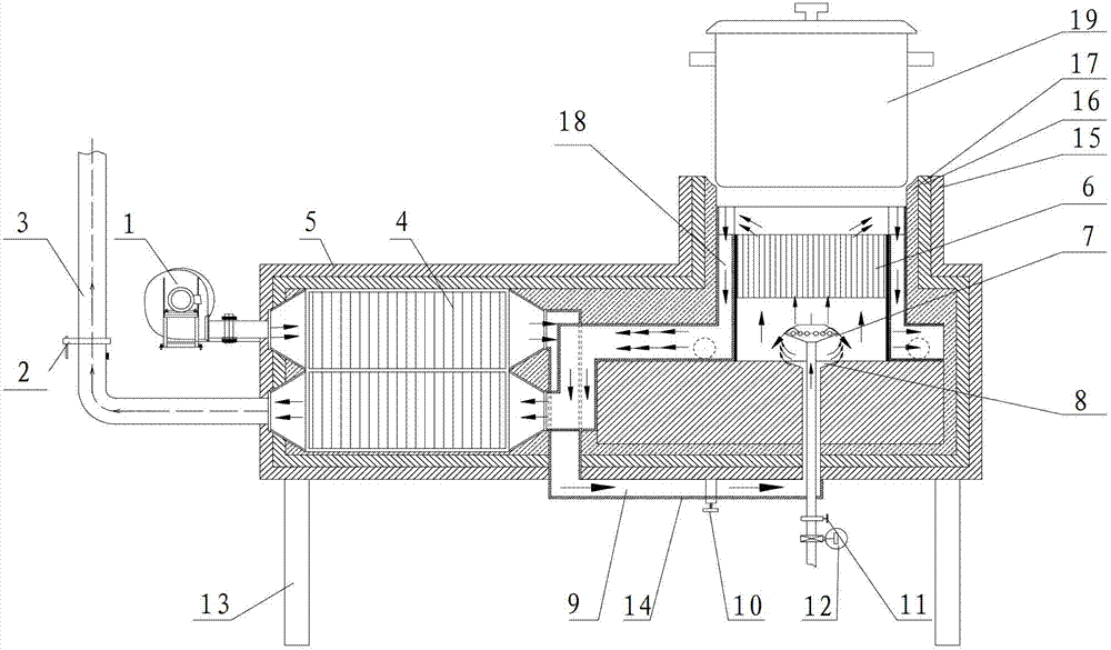
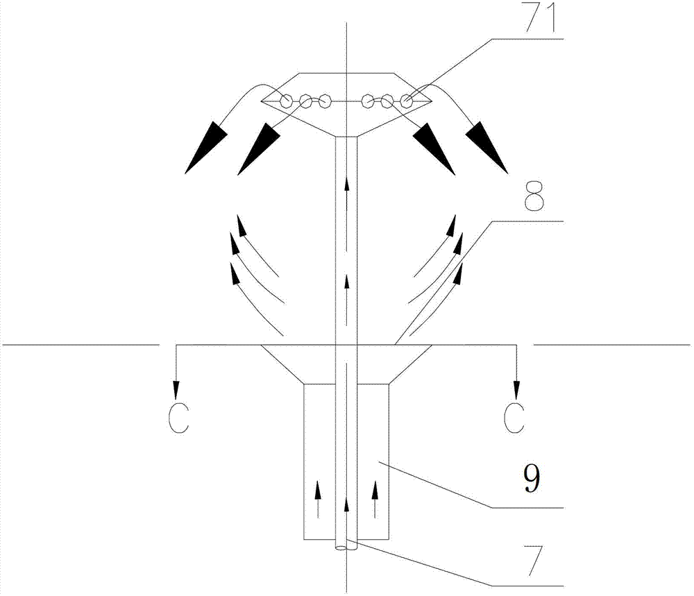
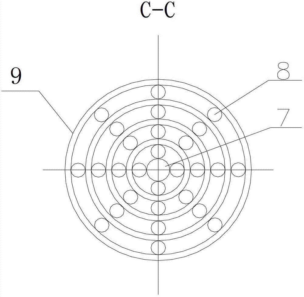
[0021] see figure 1 , figure 2 , image 3 , Figure 4 and Figure 5 The bottom of the stove body 5 is provided with a bottom support steel column 13, and the stove body 5 is provided with a hearth, and the hearth is sequentially provided with a refractory layer 17, a heat insulation layer 16, and an insulation layer 15 from the inside to the outside, and a gas pipe 7 is arranged in the hearth. The stove body 5 is provided with a hot air pipe 9 that cooperates with the gas pipe 7 to supply air. The gas pipe 7 and the hot air pipe 9 are coaxially arranged. Air outlet 8, the gas outlet of gas pipe 7 is the radial gas outlet 71 that is located on the gas pipe 7, is provided with gas control valve 11 and flowmeter 12 on the gas pipe 7, is provided with cover in the hearth of stove body 5 The porous ceramic medium 6 of the gas pipe 7 and the hot air pipe 9 forms a combustio...


PUM


Abstract

The invention discloses a waste heat recovering efficient gas stove. A hot air tube (9) for supplying air and matched with a gas tube (7) is arranged on a stove body (5), a hearth of the stove body (5) is provided with a porous ceramic medium (6) covering the gas tube (7) and the hot air tube (9) to form a combustion chamber, a smoke recovering channel (18) is formed between a side wall of the porous ceramic medium (6) and a hearth side wall of the stove body (5), a cooker can seal a hearth port when placed on the hearth port, a heat exchange tube (4) is arranged in the stove body (5), an air blower (1) is connected with an air inlet of the heat exchange tube (4), an air outlet of the heat exchange tube (4) is connected with the hot air tube (9), a smoke inlet of the heat exchange tube (4) is connected with a smoke recovering channel (18), and a smoke outlet of the heat exchange tube (4) is connected with a chimney (3). The waste heat recovering efficient gas stove can effectively improve heat efficiency, reduce pollutant discharge and improve chef working environment.

Description

technical field [0001] The invention relates to a gas stove, in particular to a waste heat recovery high-efficiency gas stove. Background technique [0002] The combustion method of the commercial gas stoves currently used in the market still adopts the traditional positive pressure open combustion method. During the gas combustion process, the combustion flame and high-temperature flue gas are directly leaked out, so that the heat generated by the gas combustion is only a small part. Utilized by pots, the heat utilization efficiency is extremely low. According to statistics, the average thermal efficiency of existing catering stoves is only 20%, and the heat loss is as high as 80%, resulting in a great waste of energy. The main reasons for the low thermal efficiency of gas cookers are as follows: [0003] (1) The heat loss of incomplete combustion of fuel is large. Due to the limitation of traditional design ideas, the gas stove in the catering industry does not support ...

Claims


Application Information

Patent Timeline
Patent Type & Authority Applications(China)
IPC IPC(8): F24C3/04F23L15/00
CPCY02B40/166Y02B40/00Y02E20/34
Inventor 陈冬林童斐
Owner HUNAN HANLON ENERGY TECH
Why Eureka
Try Eureka