Scroll compressor

A scroll compressor and scroll technology, which is applied in the field of compressors, can solve problems such as the inability to maintain long-term and stable adhesion, the inability of the structure to have mass balance, and the inability to eliminate eccentric mass, achieving excellent durability and reliability , reduced inertial mass, low cost effect

Inactive Publication Date: 2015-04-15
HITACHI LTD
View PDF10 Cites 0 Cited by
  • Summary
  • Abstract
  • Description
  • Claims
  • Application Information

AI Technical Summary

Problems solved by technology

If the base layer is only a resin material or a Ni-P plating layer, it may not be able to maintain the adhesion for a long time and stably under the conditions of use that assume considerable heat generated by sliding when exposed to high-pressure gas formed by a new refrigerant. dangerous
In particular, the aluminum substrate is very soft compared to iron, and the DLC on the surface is hard. Therefore, when the hard DLC is subjected to sliding under high pressure, the DLC deforms the base layer or the aluminum substrate, or depending on the degree of deformation And DLC also has the risk of stripping
[0016] In addition, in the technology of Patent Document 2, the reason why the Oldham ring is made of an iron-based material is to reduce the eccentric mass in the case of the orbiting scroll when the sliding member of the compressor is operated at an ultra-high speed. Eccentric rotation is performed, and the structure has a mass balance, thereby eliminating the eccentric mass. However, the Oldham ring restricts the autorotation of the orbiting scroll due to the reciprocating movement, thereby causing the compressor to orbit. Therefore, in the structure cannot have a mass balance on it, so that the eccentric mass cannot be eliminated

Method used


Image

  • Scroll compressor
  • Scroll compressor
  • Scroll compressor

Examples


Embodiment Construction

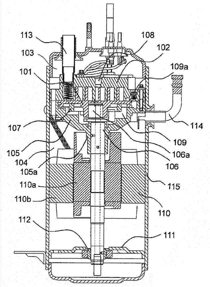
[0031] figure 1 It is a side view showing a schematic structure of the scroll compressor according to Embodiment 1 of the present invention cut along the direction in which the main axis of rotation extends.

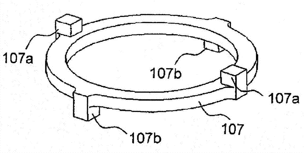
[0032] The basic structure of this scroll compressor is known in the past, and the airtight housing (chamber) 115 is provided with a suction port for installing a suction pipe 113 for sucking new refrigerant gas and a nozzle for installing and discharging the refrigerant gas. The discharge port of outlet pipe 114 is installed with the fixed scroll 102 of scroll body at the end side in the airtight casing (chamber) 115, and motor 100 is made of rotor (rotating part) 110a and stator (fixed part) 110b, crankshaft 106 is a rotating main shaft with the rotor 100a of the motor 100 installed in the approximate center, and an orbiting scroll 101 having a scroll body on the opposite side is installed on one end side of the crankshaft 106 in the axial direction via a frame 105, an...


PUM


Abstract

[Problem] To provide a scroll compressor which can contribute to reduction in the entire size and the entire weight and has excellent durability and reliability, and which can use a new refrigerant to make ultrahigh speed operation possible. [Means for Resolution] In the scroll compressor, the substrate of an Oldham-coupling ring 107 is made of an aluminum alloy, and a hard DLC layer is formed on the surface of the substrate with interposition of underlayers provided for obtaining excellent adhesion and compensating for hardness so that the weight of the Oldham-coupling ring is reduced by approximately 1 / 3, compared with the conventional case where the Oldham-coupling ring is made of an iron-based material. Adhesive wear between sliding members are prevented so that improvement in abrasion resistance and reduction in friction coefficient are achieved. As a result, the inertial mass of a rotation system is reduced. Furthermore, an orbiting scroll 101 also has the same material structure so that the eccentric mass of the rotation system is reduced. Thus, the torque load of a motor 100 can be reduced as sufficiently as possible to thereby contribute to reduction in the entire size and the entire weight to obtain excellent durability and reliability. In addition, the scroll compressor can use a new refrigerant to make ultrahigh speed operation possible so that compressing performance equivalent to the case where chlorofluorocarbon is used can be obtained.

Description

technical field [0001] The present invention relates to a compressor suitable as a refrigeration / air-conditioning circuit in an air-conditioning and hot-water supply system for next-generation houses with a high ecological (environmental response) effect, and capable of performing new refrigeration with a low global warming factor (GWP). The motor system of the agent can operate in a wide range of driving signal frequencies, and it is a scroll compressor with a compact and lightweight structure that is excellent in durability and reliability under ultra-high-speed operation. Background technique [0002] Conventionally, Oldham's rings and orbiting scrolls, which are sliding members whose sliding properties increase during operation, are generally used in scroll compressors used in refrigeration and air-conditioning circuits (also called refrigerant cycles) of air conditioners or refrigerators. Hard and highly wear-resistant iron-based material. [0003] However, Freon, whic...

Claims


Application Information

Patent Timeline
Patent Type & Authority Patents(China)
IPC IPC(8): F04C18/02F04C29/00
CPCF01C17/066F05C2203/0813F04C18/0215F04C23/008F05C2201/903F04C2230/91
Inventor 小山昌喜柳濑裕一小山田具永冈本晋哉中岛昌一冈本和孝马场升
Owner HITACHI LTD
Why Eureka
Try Eureka