Drying device and design method

A drying equipment and design method technology, applied in the direction of drying solid materials, lighting and heating equipment, heating to dry solid materials, etc., can solve the problems of long heating auxiliary time, boiler safety, high labor intensity, etc., and reduce the heating auxiliary time , high-efficiency heating function, and the effect of improving drying quality

Inactive Publication Date: 2012-11-14
西安航大炉业科技有限公司
View PDF10 Cites 9 Cited by
  • Summary
  • Abstract
  • Description
  • Claims
  • Application Information

AI Technical Summary

Problems solved by technology

High energy consumption, complicated operation, and high labor intensity. The drying methods of a, b, and c use coal directly as fuel to heat and dry materials, and the working environment is dusty, which wastes increasingly scarce resources and seriously affects operators. good health
The drying methods of d and e are to form steam through boiler roasting and heating, and dry the materials. The equipment has problems such as long drying time of materials, large energy consumption, long heating auxiliary time and boiler safety.
Regardless of the above drying methods, coal is used to transfer heat directly or indirectly. There are low heat energy utilization rates, long drying time for materials, high energy consumption, low heat conduction efficiency, and high consumption and low output of heating auxiliary equipment.
Coal smoke brings serious pollution to the surrounding environment

Method used


Image

  • Drying device and design method
  • Drying device and design method
  • Drying device and design method

Examples


Embodiment 1

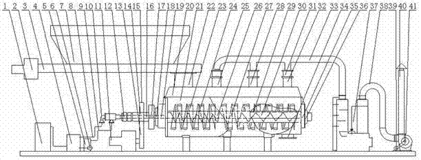
[0028] The drying equipment of the present invention at least includes a stirring propulsion mechanism, a driving mechanism, an inlet and outlet mechanism and an electric control system, and is characterized in that: there is a feed port 22 on one side of the upper part of the stirring propulsion mechanism, and a row is arranged on the other side of the upper part of the stirring propulsion mechanism. The wet tuyere, one side of the stirring propulsion mechanism is also connected with the drive mechanism transmission, the stirring feeder 21 of the stirring propulsion mechanism has an electromagnetic heating transmission stirring device, and the electromagnetic heating transmission stirring device includes an electromagnetic paddle hollow shaft 24, an electromagnetic paddle hollow shaft Inside 24 is an electromagnetic induction coil composed of a wound spiral hollow copper tube, and the tube wall of the spiral hollow copper tube is electrically connected with the electromagnetic ...

Embodiment 2

[0031] Such as figure 1 As shown, the top of the stirring bin 21 of the stirring propulsion mechanism in the above-mentioned embodiment is fixed with a bin cover 20, the left side of the bin lid 20 is the feed inlet 22, the right side is the humidity outlet, and the bottom of the right side of the stirring bin 21 is the outlet. The feed port 34, the insulation layer 42 is arranged in the silo wall of the stirring silo 21, and the electromagnetic heating transmission stirring device is arranged in the stirring hopper 21, and the electromagnetic heating transmission stirring device includes a paddle screw blade 23, an electromagnetic paddle hollow shaft 24, an electromagnetic induction Coil, the left and right ends of electromagnetic paddle hollow shaft 24 are respectively connected with front bearing seat 19 and rear bearing seat 35 bearings, and front bearing seat 19 and rear bearing seat 35 are respectively placed in the front bearing cover 18 and the left and right ends of st...

Embodiment 3

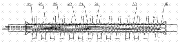
[0034] Such as figure 2 As shown, the electromagnetic induction coil in the electromagnetic paddle hollow shaft 24 is composed of a high-temperature electromagnetic induction coil 26, a coil cooling pipe 27, and a low-temperature electromagnetic induction coil 30 to form a multi-temperature zone electromagnetic induction coil. Directly run through the hollow shaft 24 of the electromagnetic paddle and extend to the rear end 45 of the water inlet copper tube, and then spirally wind the hollow copper tube through the section in reverse to form a helical electromagnetic induction coil, which is located on the left side of the hollow shaft 24 of the electromagnetic paddle The number of turns of the spiral electromagnetic induction coil is more to form a high-temperature electromagnetic induction coil 26, and the number of turns of the spiral electromagnetic induction line on the right side of the electromagnetic blade hollow shaft 24 is less to form a low-temperature electromagneti...


PUM


Abstract

The invention relates to a drying device and a design method. The drying device at least comprises a stirring pushing mechanism, a driving mechanism, an inlet-outlet mechanism and an electronic control system and is characterized in that a feeding port is arranged on one side of the upper portion of the stirring pushing mechanism, a moisture exhaust port is arranged on the other side of the upperportion of the stirring pushing mechanism, one side of the stirring pushing mechanism is further in transmission connection with the driving mechanism, an electromagnetic heating transmission stirring device is arranged in a stirring bin of the stirring pushing mechanism, the electromagnetic heating transmission stirring device comprises an electromagnetic blade hollow shaft, an electromagnetic induction coil formed by a winding spiral hollow copper pipe is arranged in the electromagnetic blade hollow shaft, the pipe wall of the spiral hollow copper pipe is electrically connected with an electromagnetic conductive slip ring of the electronic control system. The drying device can effectively improve energy utilization rate and is low in energy consumption, high in production capacity and automatic control, high-tech and environment-friendly.

Description

technical field [0001] The invention relates to the fields of smelting and nonferrous metals and chemical industry, in particular to a drying equipment and a design method. Background technique [0002] In recent years, with the modernization of my country's industry, the requirements for drying equipment have become higher and higher. Higher requirements are put forward for environmental protection, energy saving and high efficiency. At present, the drying methods in the domestic market mainly include: a flash drying, b boiling drying, c hot air furnace, d box drying, e double cone rotary vacuum drying, etc. High energy consumption, complicated operation, and high labor intensity. The drying methods of a, b, and c use coal directly as fuel to heat and dry materials, and the working environment is dusty, which wastes increasingly scarce resources and seriously affects operators. of good health. The drying methods of d and e are to form steam through boiler roasting and he...

Claims


Application Information

Patent Timeline
Patent Type & Authority Applications(China)
IPC IPC(8): F26B17/20F26B3/347F26B23/08F26B25/00F26B25/02
Inventor 朱树伟
Owner 西安航大炉业科技有限公司
Why Eureka
Try Eureka