Sensor with a plurality of magnet positions and magnetic flux both unevenly distributed in housing

A technology of uniform distribution and magnetic flux, applied in the direction of conversion of sensor output, instruments, power measurement, etc., can solve problems such as different, lack of assistance, and discomfort for cyclists

Inactive Publication Date: 2012-11-28
CHONGQING SINYM TECH CO LTD
View PDF5 Cites 1 Cited by
  • Summary
  • Abstract
  • Description
  • Claims
  • Application Information

AI Technical Summary

Problems solved by technology

[0015] Disadvantages (1) Using two permanent magnets with no difference to represent the fixed positions of the two pedals, only multiple Halls can be used to represent the pedals Rotation position: There is no difference between the two permanent magnets. The advantage is that the fixed positions of the two pedals can be expressed regardless of the left and right feet, so that the left and right feet can generate power assistance requirements, which can produce the same motor power assistance effect; but the disadvantage is that The permanent magnetic steel itself cannot indicate the rotation position of the pedal, but can only use multiple Halls at different corner positions to indicate the rotation position of the pedal, so it is not possible to use only one Hall, but must use multiple Halls
[0016] Disadvantage (2) Only one Hall cannot be used, but three Halls will inevitably cause the original segmentation error of the three control signals, which will distort the power-assist demand model, naturally The generation of power output is inconsistent with the demand for power assistance: no matter whether the power-assisted bicycle has one or two motors, the sensor signal for controlling the motor can only be controlled by using one sensor signal input to the motor controller; and the patent uses three sensors. If Hall controls the motor, the three control signals of the three Halls must be combined into one combined control signal before it can be input to the motor controller
The sensing parameters of the three Halls cannot be the same, especially due to changes in ambient temperature and long-term use, the sensing parameters of the three Halls may vary greatly. The output voltages are different, resulting in different power output of the motor, and the power output is inconsistent with the power demand; similarly, when the power demand is the same, the outputs of different Halls may be the same voltage, resulting in the same power output of the motor, and also There is a problem that the power output is inconsistent with the power demand
[0019] Disadvantages (5) The signal blind area reaches 42 degrees, and when the power is needed when starting, it is impossible to get it: as we all know, the torque of the bicycle pedal is the smallest at the apex , from the angle of 10-45 degrees away from the top is the area that needs the most assistance, but the angle between the Halls in this patent is 42.5-43.5 degrees, and there is no Hall in the area of ​​10-42 degrees away from the top of the pedal. There is no control signal, and the result is when the assist is most needed, but the motor of the assist bicycle cannot assist
[0020] In short, this patent is a technical solution for using multiple Halls to control the booster mode, because only multiple Halls can be used to represent the rotation position of the pedal, and the multiple control signals of multiple Halls must have original errors, and the combined control signals It is also easy to produce signal drift, which can cause distortion of the assist demand model, that is, the same assist demand at different times, but different assist effects; the more the number of Halls, the more serious the distortion of the assist demand model, limiting the number of Halls , a small amount of Hall will cause the motor to run unsteadily, making the rider feel very uncomfortable, and will not get assistance when starting
To make it undistorted to help the demand model, and to ensure the smooth operation of the motor, there are always two issues. It is impossible to have both.

Method used


Image

  • Sensor with a plurality of magnet positions and magnetic flux both unevenly distributed in housing
  • Sensor with a plurality of magnet positions and magnetic flux both unevenly distributed in housing
  • Sensor with a plurality of magnet positions and magnetic flux both unevenly distributed in housing

Examples


Embodiment 1

[0112] Embodiment 1. A sensor with non-uniform distribution of magnetic block positions and magnetic fluxes in the housing

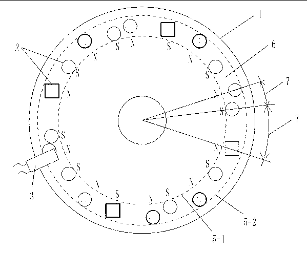
[0113] Such as figure 1 , 3 , 4. The sensor in this embodiment includes a sensing element connected in sequence, a booster model processor 21, a digital-to-analog converter 27 and an operational amplifier 28;

[0114] [1] The sensing element is an element that converts the rotational motion of the annular groove rotating disk 1 into a rectangular wave signal output;

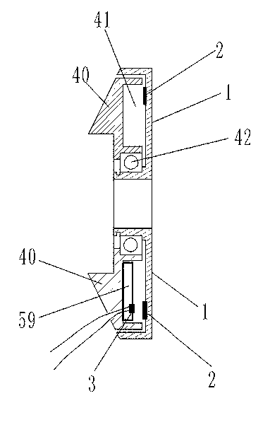
[0115] The concave surfaces of an annular groove rotating disk 1 and an annular groove fixing disk 40 are opposite, and the size of the annular groove rotating disk 1 and the annular groove fixing disk 40 is just enough to make the annular groove fixing disk 40 fit in the ring. In the annular groove of the groove rotating disk 1, two disks are synthesized into a fitting inner hollow shell that can rotate relatively, and the concave surfaces of the two disks are sandwiched into a hollow r...

Embodiment 2

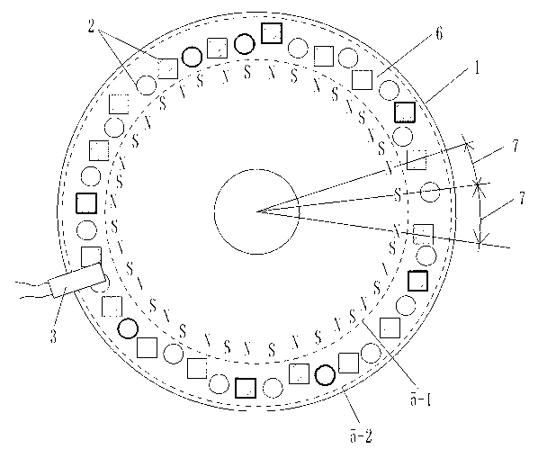
[0133] Embodiment 2, high-density sensor with non-uniform distribution of multi-magnetic block positions and magnetic fluxes in the housing

[0134] Such as figure 2 , 3 , 4, the annular groove rotating disk 1 surface diameter in the hollow ring 41 is 10.0 centimeters, establishes 40 permanent magnet pieces 2 in the annular groove rotating disk 1, and the diameter of 40 permanent magnet pieces 2 is respectively 0.6 centimetre, and the magnetic flux is 146---279(B·H)max / KJ·m -3 Different selection values ​​within the range, and the magnetic flux of adjacent permanent magnet block 2 is not equal. Hall 3 keeps a distance of 0.2 cm from each permanent magnet 2 in the rotating state, so that when each rotating permanent magnet 2 passes through Hall 3, Hall 3 can generate a corresponding rectangular wave electric signal output. The structures of other annular groove rotating disk 1, permanent magnet block 2 and Hall 3 are the same as those in embodiment 1.

Embodiment 3

[0135] Embodiment 3, a sensor with a specific circuit in which the positions of multiple magnetic blocks and the magnetic flux are unevenly distributed in the housing

[0136] Such as figure 1 , 3 , 5. The sensor in this embodiment includes a sensing element connected in sequence, a booster model processor 21, a digital-to-analog converter 27 and an operational amplifier 28;

[0137] [1] The Hall 3 in the sensing element is UGN3075; the structure of other elements and elements in the sensing element is the same as that in Embodiment 1;

[0138] [2] The auxiliary model processor 21 selects the single-chip microcomputer 31 to complete all functions, and the single-chip microcomputer 31 selects AT89S52. That is, the AT89S52 single-chip microcomputer 31 completes all functions of the analog-to-digital conversion and the wave width peak recognizer 22 , the power-assisted starting point selector 23 , the magnet speed calculator 24 , the power-assisted model memory 25 and the powe...


PUM


Abstract

The invention provides a sensor with a plurality of magnet positions and magnetic flux both unevenly distributed in a housing, belonging to the technology of providing a control signal through multi-point position magnetic induction. The sensor comprises a sensing element, a power model processor, a digital-to-analogue converter and an operational amplifier which are sequentially connected, wherein the sensing element comprises a rotating disc and a fixed disc; permanent magnets and a hall are embedded in the inner cavity of the fixed disc; a plurality of permanent magnets different in spacing and magnetic flux are fixedly arranged on the rotating disc; the adjacent permanent magnets are opposite in magnetic polarity, namely, the distribution manner of the magnetic polarities of all permanent magnets on one surface of the rotating disc are pole N, pole S, pole N...; and the hall on the fixed disc is arranged in a position in the vicinity of the permanent magnets. The sensor has the following advantages that the magnetic polarities are in N-S distribution so that the hall is capable of obtaining a rectangular wave signal, which can be added for digital processing of a set power model; the rectangular wave signal is capable of indicating the positions of the permanent magnets on the rotating disc; therefore, the uses of different rectangular waves are determined; and the relative positions of the permanent magnets and the hall are fixed and the signal output is reliable.

Description

technical field [0001] The invention belongs to the technical field of providing signals by magnetic induction, and in particular relates to the technology of providing control signals by multi-point magnetic induction on a rotating component. Background technique [0002] The Chinese patent 201020295192.0 "Claw Type Torque Sensing Device" applied by Yebao Vehicle Material Industry (Kunshan) Co., Ltd. discloses a sensing device for power-assisted bicycles. The sensing device includes a magnetic part and an elastic part to sense the torque. sensing device. After a long time of use, the change of the elastic coefficient of the elastic member will lead to changes in the sensing signal and the control effect of the controlled motor, and the power-assisted effect will not match the power-assisted needs of people. Moreover, the design structure of the elastic member is complex and the manufacturing cost is high. [0003] The Chinese patent 01201843.0 "Automatic Detection Device ...

Claims


Application Information

Patent Timeline
Patent Type & Authority Applications(China)
IPC IPC(8): B62M6/50G01L3/00G01P3/481
CPCG01P3/481G01D5/246G01P3/487G01L3/00B62M6/50G01D5/2492G01D5/2455
Inventor 黄强
Owner CHONGQING SINYM TECH CO LTD
Why Eureka
Try Eureka