Gas-direct-contact-type ice slurry generator

A generator, contact technology, applied in the direction of ice making, ice making, heating methods, etc., can solve the problems of ice making solution leakage, increased maintenance cost, easy occurrence of ice blockage, etc., to increase movement resistance and save investment costs. , the effect of reducing maintenance costs

Inactive Publication Date: 2012-12-12
ZHEJIANG UNIV
View PDF5 Cites 2 Cited by
  • Summary
  • Abstract
  • Description
  • Claims
  • Application Information

AI Technical Summary

Problems solved by technology

[0003] However, the aforementioned ice slurry production system has the following problems: 1. After the ice-making solution at the nozzle of the ice slurry generator is overcooled, the ice crystals accumulate seriously, and ice blockage is very easy to occur, which affects the stable operation of the system; 2. The ice slurry generator contains ice. When the cooling rate (IPF) increases, the convective heat transfer effect between the cooling gas and the ice-making solution is weakened, which affects the heat transfer efficiency of the system; 3. During the operation of the system, the ice-making solution leaks a lot from the nozzle, and the maintenance cost increases

Method used


Image

  • Gas-direct-contact-type ice slurry generator
  • Gas-direct-contact-type ice slurry generator
  • Gas-direct-contact-type ice slurry generator

Examples


Embodiment Construction

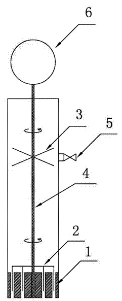
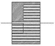
[0016] As shown in the figure, the gas direct contact ice slurry generator includes a concentric ring nozzle 1, a deicer 2, an agitator 3, a transmission shaft 4, an ice outlet 5, and a drive motor 6; the lower end of the generator body is provided with a concentric ring nozzle 1. There is a drive shaft 4 in the center of the generator body, an agitator 3 is installed on the drive shaft 4, a drive motor 6 is installed above the generator body, an ice outlet 5 is provided on the side wall of the upper part of the generator body, and the upper end of the drive shaft 4 is connected to The driving motor 6 is connected, the lower end of the transmission shaft 4 is connected with the deicer 2, the deicer 2 includes a bracket 7 and a deicing blade 8, the lower surface of the bracket 7 is vertically provided with a deicing blade 8, and the bracket 7 is provided with 1 to 3 arms , the lower end of the deicing blade 8 extends into the annular channel of the concentric ring nozzle 1, the ...


PUM


Abstract

The invention discloses a gas-direct-contact-type ice slurry generator. The generator comprises a concentric annular spray-nozzle, a de-icer, a stirrer, a drive shaft, an ice outlet, and a driving motor. The concentric annular spray-nozzle is arranged at the lower end of a generator body. The drive shaft is arranged at the center of the generator body. The stirrer is arranged on the drive shaft. The driving motor is arranged above the generator body. The ice outlet is provided on the side wall on the upper part of the generator body. The upper end of the drive shaft is connected with the driving motor. The lower end of the drive shaft is connected with the de-icer. The de-icer comprises a support and de-icing blades. The de-icing blades are vertically arranged on the lower surface of the support. The support is provided with 1-3 arms. The lower ends of the de-icing blades extend into annular flow channels of the concentric annular spray-nozzle. The number of the de-icing blades on a single support arm is the same with that of the annular flow channels of the concentric annular spray-nozzle. An ice-making solution is provided in the generator body. With the generator provided by the invention, ice blockage can be effectively prevented, and system ice-making solution leakage can be reduced. The ice slurry is stirred, such that a heat exchange effect is reinforced. Therefore, the stable and highly efficient operation of the ice slurry preparation system is promoted.

Description

technical field [0001] The invention relates to the field of energy air conditioning, in particular to a gas direct contact type ice slurry generator. Background technique [0002] Gas direct contact method ice slurry production system [Patent No. ZL 2009 1 0102116.5] uses air, nitrogen and other environmentally friendly working fluids as refrigerants to directly contact and exchange heat with ice-making solution to produce ice slurry. The use of gas as the refrigerant can reduce system investment and maintenance costs, and at the same time avoid the problem of cold storage liquid pollution caused by the liquid refrigerant dissolving into the ice-making solution. [0003] However, the aforementioned ice slurry production system has the following problems: 1. After the ice-making solution at the nozzle of the ice slurry generator is overcooled, the ice crystals accumulate seriously, and ice blockage is very easy to occur, which affects the stable operation of the system; 2. T...

Claims


Application Information

Patent Timeline
Patent Type & Authority Applications(China)
IPC IPC(8): F25C1/00F25C5/12F24F5/00
Inventor 张学军王炜王晓蕾江敏
Owner ZHEJIANG UNIV
Why Eureka
Try Eureka