Flow energy storage battery structure

A liquid flow energy storage battery and battery technology, which can be used in fuel cells, regenerative fuel cells, and fuel cell components, etc., can solve the problems of limited improvement in voltage efficiency and energy efficiency, and improve energy efficiency and voltage efficiency. , reduce the body resistance, reduce the effect of ohmic polarization

Inactive Publication Date: 2013-01-09
DALIAN INST OF CHEM PHYSICS CHINESE ACAD OF SCI +1
View PDF4 Cites 18 Cited by
  • Summary
  • Abstract
  • Description
  • Claims
  • Application Information

AI Technical Summary

Problems solved by technology

However, the ohmic internal resistance of the all-vanadium redox flow energy storage battery mainly includes the bulk resistance of the electrode, bipolar plate, electrolyte and separator, and the contact resistance between the electrode and the bipolar plate.
This method only reduces the contact resistance between the electrode bipolar plates, and has no effect on the bulk resistance of the electrodes and electrolyte, which account for a large proportion of the internal resistance of the battery, so the improvement of voltage efficiency and energy efficiency is limited.

Method used


Image

  • Flow energy storage battery structure
  • Flow energy storage battery structure
  • Flow energy storage battery structure

Examples


Embodiment 1

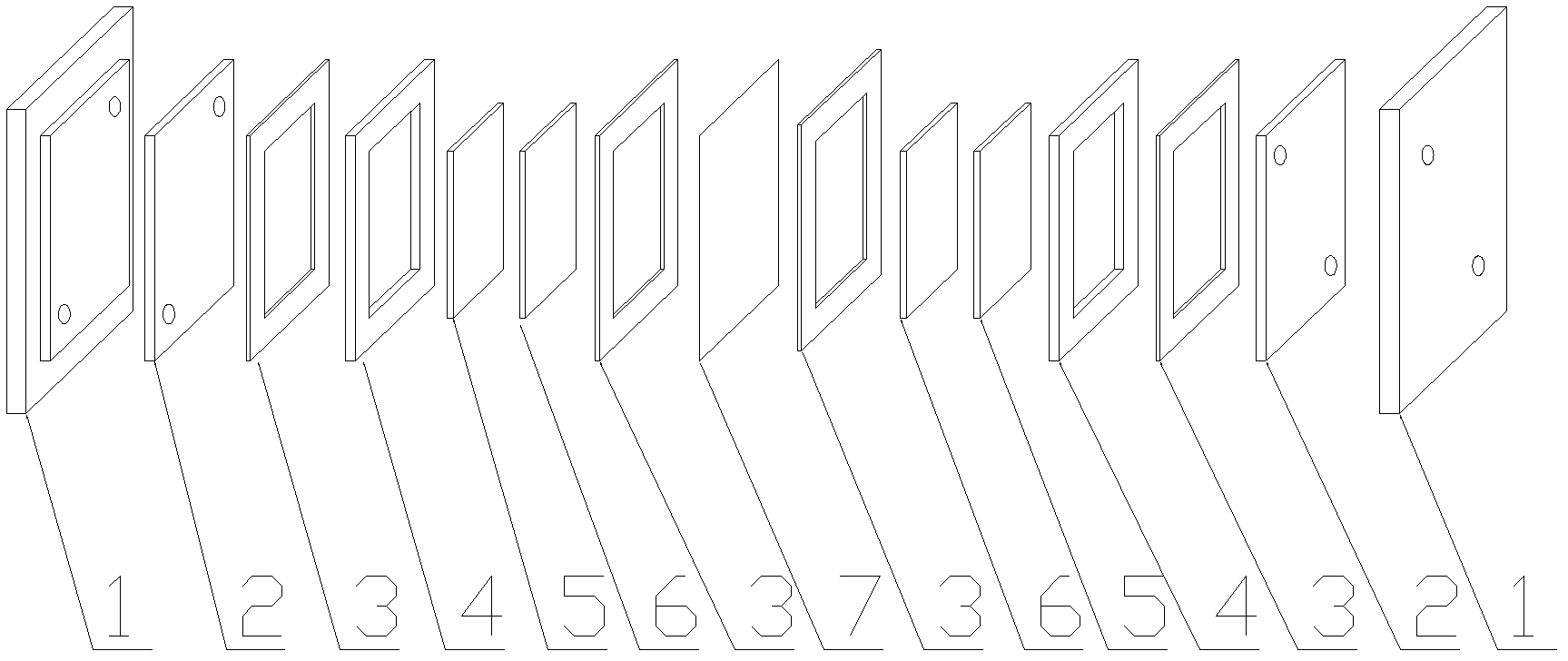
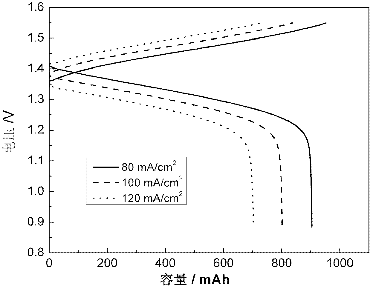
[0030] according to figure 1 The structure shown is assembled into an all-vanadium liquid flow energy storage single cell, in which the electrode frame 4 is 3 mm thick, the filler plate 5 uses a 2 mm thick non-porous graphite plate, the electrode 6 is a 3 mm thick carbon felt, and the non-porous graphite plate and carbon felt The area is 12cm 2 , the sealing gasket 3 is 0.5mm thick silicone rubber; the initial positive electrode electrolyte is 1.5M VO 2+ 3M H 2 SO 4 Solution 40ml, the initial negative electrode electrolyte is 1.5M V 3+ 3MH 2 SO 4 Solution 40ml. The battery charge termination voltage is 1.55V, and the discharge termination voltage is 0.9V. The charging and discharging curves and battery efficiency of the battery at different current densities are as follows: figure 2 and shown in Table 1. The single battery adopting the battery structure of the present invention has a current density of 80mA / cm 2 , the voltage efficiency and energy efficiency were 90...

Embodiment 2

[0033] according to figure 1 The structure shown is assembled into an all-vanadium flow energy storage single cell, in which the electrode frame 4 is 3mm thick, and the filling plate 5 uses a 2mm thick flexible graphite plate, and the density of the flexible graphite plate is 1.5g / cm 3 , the porous electrode 6 is a 3mm thick carbon felt, and the area of ​​the flexible graphite plate and the carbon felt is 12cm 2 , the sealing gasket 3 is 0.5mm thick silicone rubber; the initial positive electrode electrolyte is 1.5M VO 2+ 3M H 2 SO 4 Solution 40ml, the initial negative electrode electrolyte is 1.5M V 3+ 3M H 2 SO 4 Solution 40ml. The battery charge termination voltage is 1.55V, and the discharge termination voltage is 0.9V.

[0034] The cell efficiency of the single cell in this embodiment at different current densities is shown in Table 1, and the current density is increased to 120mA / cm 2 , the voltage efficiency and energy efficiency still remain at 84.3% and 81.4%....

Embodiment 3

[0036] according to figure 1 The structure shown is assembled into an all-vanadium liquid flow energy storage single cell, in which the electrode frame 4 is 3 mm thick, and the filling plate 5 uses a 1 mm thick flexible graphite plate, and the density of the flexible graphite plate is 1.5 g / cm 3 , the porous electrode 6 is a 4mm thick carbon felt, and the area of ​​the flexible graphite plate and the carbon felt is 12cm 2 , the sealing gasket 3 is 0.5mm thick silicone rubber; the initial positive electrode electrolyte is 1.5M VO2+ 3M H 2 SO 4 Solution 40ml, the initial negative electrode electrolyte is 1.5M V 3+ 3M H 2 SO 4 Solution 40ml. The battery charge termination voltage is 1.55V, and the discharge termination voltage is 0.9V.

[0037] The cell efficiency of the single cell in this embodiment at different current densities is shown in Table 1, and the current density is increased to 120mA / cm 2 , the voltage efficiency and energy efficiency remained at 82.4% and 79...


PUM

PropertyMeasurementUnit
densityaaaaaaaaaa

Abstract

The invention relates to a flow energy storage battery structure, characterized in that an infill panel is arranged between a bipolar plate and a porous electrode in an electrode frame, the infill panel is made from carbon materials with good electrical conductivity and low porosity or metal materials which are stable in acidic mediums, reduces the body resistances of the electrodes and electrolyte and contact resistance between the electrode bipolar plates to finally reduce the ohmic resistance of the flow energy storage battery. According to the invention, the energy efficiency and voltage efficiency of the flow energy storage battery are raised, so that the working current density is raised, and the weight, volume and cost of the battery with same output power are greatly reduced.

Description

technical field [0001] The invention relates to the technical field of liquid flow energy storage batteries, in particular to a structure of an all-vanadium flow energy storage battery. Background technique [0002] All-vanadium redox flow energy storage battery has independent output power and capacity, flexible system design; high energy efficiency, long life, high operation stability and reliability, low self-discharge; large degree of freedom in site selection, no pollution, easy maintenance It has the advantages of simplicity, low operating cost, and high safety. It has broad development prospects in large-scale energy storage. It is considered to be an effective method to solve the random and intermittent unsteady characteristics of renewable energy generation systems such as solar energy and wind energy. There are significant demands in renewable energy power generation and smart grid construction. [0003] However, the working current density of the all-vanadium red...

Claims


Application Information

Patent Timeline
Patent Type & Authority Applications(China)
IPC IPC(8): H01M8/18H01M8/02H01M8/0234H01M8/2455
CPCY02E60/528Y02E60/50
Inventor 张华民刘涛赖勤志刘宗浩
Owner DALIAN INST OF CHEM PHYSICS CHINESE ACAD OF SCI
Why Eureka
Try Eureka