Mini-type combined type energy collector based on PVDF (Poly Vinyli Dene Fluoride) and preparation method

An energy harvester and composite technology, applied in the field of micro-electromechanical systems, can solve the problems of small current and low output power, and achieve the effects of simple preparation process, increased output power and improved efficiency

Inactive Publication Date: 2013-01-09
PEKING UNIV
View PDF4 Cites 20 Cited by
  • Summary
  • Abstract
  • Description
  • Claims
  • Application Information

AI Technical Summary

Problems solved by technology

However, due to the extremely large internal resistance of piezoelectric materials, the output current is very small. When a single piezoelectric energy harvesting is used, the output power is still low

Method used


Image

  • Mini-type combined type energy collector based on PVDF (Poly Vinyli Dene Fluoride) and preparation method
  • Mini-type combined type energy collector based on PVDF (Poly Vinyli Dene Fluoride) and preparation method
  • Mini-type combined type energy collector based on PVDF (Poly Vinyli Dene Fluoride) and preparation method

Examples


Embodiment 1

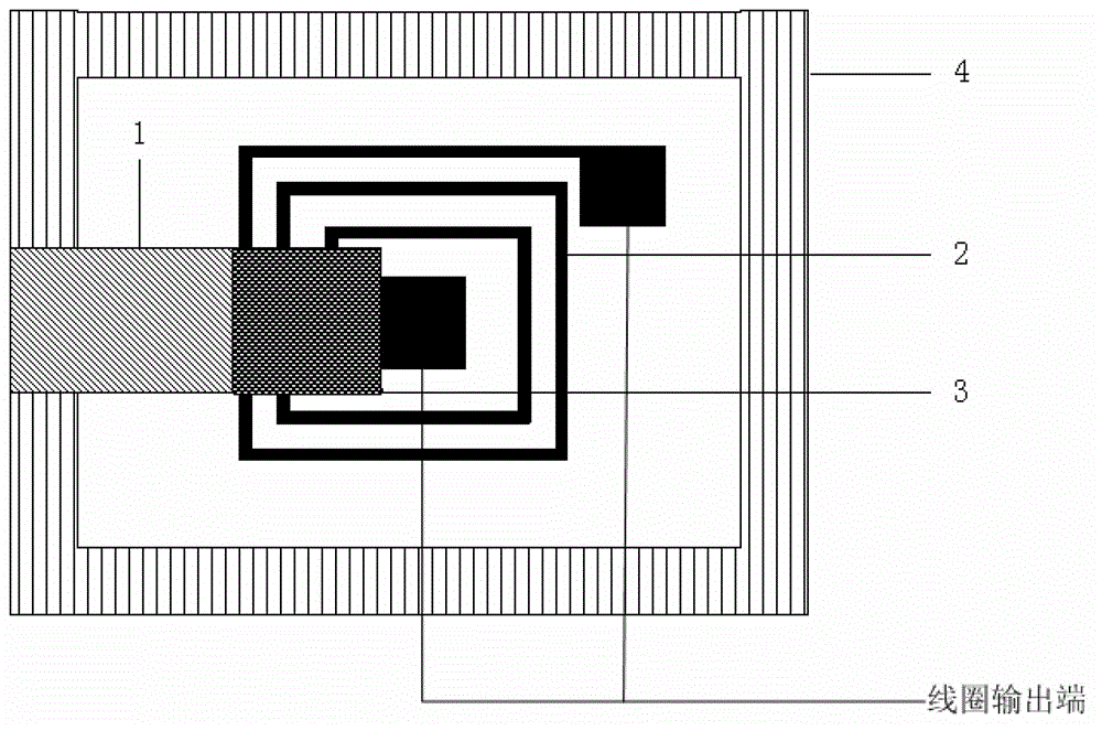
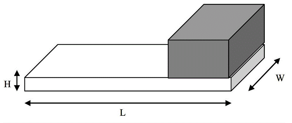
[0048] A piezoelectric and electromagnetic composite MEMS energy harvester, including a substrate, a PVDF piezoelectric film, a planar spiral coil 2, a PDMS mass block 3 containing magnetic nanoparticles, and a flexible support 4, i.e. a PDMS support frame, such as figure 1 shown. The PVDF piezoelectric film is made into a cantilever beam structure, and the substrate is deposited with a layer of SiO on the surface 2 composed of silicon wafers, the planar spiral coil 2 is electroplated on SiO 2 layer, the flexible support 4 is also located on the SiO 2 Layer, and located around the planar helical coil 2. The PVDF piezoelectric film is cut into a cantilever structure, and the PDMS mass block 3 containing magnetic nanoparticles is fixed on the free end of the PVDF piezoelectric cantilever 1, and the other end of the PVDF piezoelectric cantilever 1 is fixed on the flexible support 4, as figure 2 shown. The free end of the PVDF piezoelectric cantilever beam 1 is the output end...

Embodiment 2

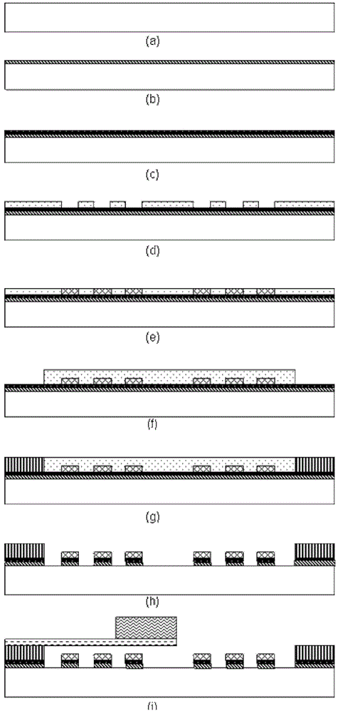
[0063] A preparation method of a piezoelectric and electromagnetic composite MEMS energy harvester, using a three-dimensional micromachining method combining bulk silicon and surface micromachining techniques, including a substrate, a PVDF piezoelectric film, a planar helical coil 2, and magnetic nanoparticles The PDMS mass block 3 also includes a vibration window 5, as shown in FIG. 6 . That is, the silicon is etched by bulk silicon micromachining technology to form the vibration window of the PVDF piezoelectric cantilever beam, and the planar spiral coil 2 is fabricated on the silicon chip by surface micromachining.

[0064] The manufacturing steps are roughly the same as those in Embodiment 1, except that after the planar spiral coil 2 is manufactured, the vibration window 5 is manufactured using wet etching technology instead of the flexible support 4 .

[0065] Step (3) is to make the vibration window, the process is as follows Figure 7 As shown, specifically:

[0066]...


PUM

PropertyMeasurementUnit
thicknessaaaaaaaaaa

Abstract

The invention provides a mini-type combined type energy collector based on PVDF (Poly Vinyli Dene Fluoride) and a preparation method. A cantilever structure is prepared by using a flexible polymer piezoelectric material PVDF, resonance is generated through the PVDF piezoelectric cantilever, and vibration is converted into electric energy by using a piezoelectric effect; and meanwhile, a PDMS (Poly Di Methyl Siloxane) mass block containing nanometer particles, which is fixedly connected with the mini-type combined type energy collector, vibrates with the vibration of the PVDF piezoelectric cantilever, so that the magnetic flux of passing through a plane spiral coil electrically plated on a substrate can be varied, and sensing electromotive force is generated. Therefore, output power is externally loaded. The mini-type combined type energy collector provided by the invention uses a polymer piezoelectric material PVDF to replace a traditional piezoelectric material PZT (Piezoelectric Transducer), and energy collection can be carried out through a piezoelectric manner and an electromagnetic manner, so that the output power and the efficiency of the energy collector can be obviously improved, and the mini-type combined type energy collector is biologically compatible.

Description

technical field [0001] The invention relates to a micro-energy collector based on a polymer piezoelectric material PVDF and a preparation method thereof, belonging to the field of micro-electromechanical systems. Background technique [0002] With the rapid development of micro-nano technology, a large number of new micro-nano devices and systems have been continuously developed, such as micro-generators, nano-structured optoelectronic devices, nano-drug delivery and targeted therapy for disease prevention and treatment, etc. However, micro-nano The power supply problem of nano products is becoming the main obstacle to its application, because the power supply of these micro and nano systems mainly relies on batteries. In order to avoid frequent battery replacement, this requires the battery's working life to be continuously extended, and in some special micro-nano products or devices, especially in implanted systems (such as cardiac pacemakers, implanted sensors, etc.) , r...

Claims


Application Information

Patent Timeline
Patent Type & Authority Applications(China)
IPC IPC(8): H02N2/18H02N11/00B81B3/00B81C1/00
Inventor 张海霞贾若溪袁泉韩梦迪
Owner PEKING UNIV
Why Eureka
Try Eureka