Device and method for measuring long stroke displacement based on Hall effect

A technology of displacement measurement and Hall effect, which is applied in the direction of measuring devices, electric devices, buoy liquid level indicators, etc., can solve the problems of increased circuit complexity, inability to measure effectively, and large measurement range, so as to reduce the number of welding, The effect of reducing the power and expanding the measurement range

Inactive Publication Date: 2013-01-16
杨会峰
View PDF8 Cites 22 Cited by
  • Summary
  • Abstract
  • Description
  • Claims
  • Application Information

AI Technical Summary

Problems solved by technology

The switch-type Hall sensor is an active device, coupled with the auxiliary circuit, the measurement range will not be able to realize the thin strip device
[0012] 3. Using a switch-type Hall sensor, as the measurement length increases, the circuit complexity increases exponentially, and its low-power measurement method will be meaningless
[0013] 4. Using a switch-type Hall sensor, as the measurement length increases, the complexity of the circuit increa

Method used


Image

  • Device and method for measuring long stroke displacement based on Hall effect
  • Device and method for measuring long stroke displacement based on Hall effect
  • Device and method for measuring long stroke displacement based on Hall effect

Examples


Embodiment Construction

[0033] The present invention will be described below through the embodiments and accompanying drawings, but the present invention is not limited thereto.

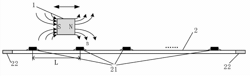
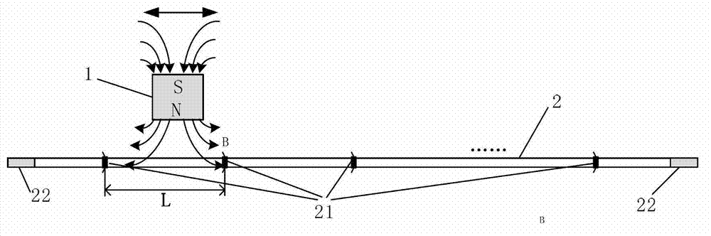
[0034] The invention improves the magnetic float liquid level gauge, and uses the Hall effect to measure the displacement of the long-stroke magnetic float. The magnetic float includes a magnet, so in each drawing of the present invention, the magnetic direction of the magnetic float is expressed by the magnetic direction of the magnet. The present invention mainly includes two parts, a sensor part and a measuring part, and the sensor part will be introduced first below.

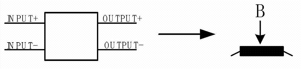
[0035] The sensor used in the present invention is a linear Hall sensor array, figure 1The pin definition of the single linear Hall sensor used and the schematic diagram of the direction of the measured magnetic field are given. The left half is a schematic diagram of pin definitions. INPUT+ and INPUT- are respectively the positive and negative input p...


PUM


Abstract

The invention belongs to the technical field of physical parameter measurement and relates to a device for measuring long stroke displacement based on the Hall effect. The device comprises a single chip microcomputer, a constant current source, a signal processing circuit, an analog-to-digital converter and a sensor array, wherein the sensor array is at least one group of linear hall sensors; each group of the linear hall sensors are uniformly and linearly arranged on a PCB (Printed Circuit Board); the space between the adjacent linear hall sensors is not less than the size of a magnet on a magnetic float in the arrangement direction of the sensor array; the differential outputs of the linear sensors are multiplexed with two differential voltage signal transmission lines through an n-channel analog multiplexer; the two differential voltage signal transmission lines are connected with an input interface of the signal processing circuit; the two adjacent PCBs are connected through an expansion interface; and each group of the linear hall sensors are powered by one same constant current source in a time sharing manner. The device has the advantages of low power consumption, fewer adopted devices, convenience in maintenance and lower cost.

Description

technical field [0001] The invention belongs to the technical field of physical parameter measurement, and relates to a Hall effect displacement measuring device and a measuring method, in particular to a Hall displacement measuring device and a measuring method for long-stroke displacement measurement through a linear Hall sensor. Background technique [0002] At present, the transmitter part of the magnetic float level gauge uses a reed switch sensor. Some technical parameters of the transmitter of the magnetic float level gauge: [0003] Liquid density: >0.4g / cm3, [0004] Maximum range: 0-6m, [0005] Resolution: ±1cm, [0006] Signal transmission mode: (4-20) mA (two-wire system). [0007] Magnetic float level gauge is a kind of liquid level instrument that has certain requirements for measurement accuracy (resolution: ±1cm), but the requirements are not too high, and its price is relatively moderate. If higher accuracy is required, such as ±1mm accuracy, other ...

Claims


Application Information

Patent Timeline
IPC IPC(8): G01B7/02G01F23/30
Inventor 杨会峰
Owner 杨会峰
Why Eureka
Try Eureka