Method for catalytic hydrolysis of freon and device thereof
A technology of catalytic hydrolysis and freon, applied in the field of catalytic decomposition of chlorofluoroalkanes, can solve the problems of high cost, inability to recover effective substances, pollutants, etc., and achieve the effects of long service life, cheap and easy-to-obtain catalysts, and low reaction temperature
- Summary
- Abstract
- Description
- Claims
- Application Information
AI Technical Summary
Problems solved by technology
Method used
Image

Examples
Embodiment 1
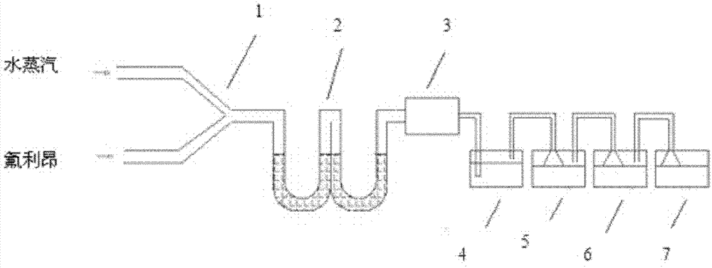
[0015] figure 1 Is the process flow chart of this embodiment. like figure 1 As shown, water vapor and freon are respectively passed into the tee pipe 1 from both ends, and then pass through the U-shaped reactor 2. The U-shaped reactor has two sections, the first section is connected to the tee pipe, and the second section is connected to the heat exchanger. The U-shaped reactor is equipped with a mixture of aluminum sulfate, aluminum phosphate, and iron phosphate (aluminum sulfate, aluminum phosphate, and iron phosphate are dried and dehydrated, passed through a 100-200 mesh sieve, and then according to the molar ratio of 1:0.3~1:0.3~ 1 mixing), the mixed gas passes through the U-shaped reactor, then exchanges and cools through the heat exchanger 3, and then enters the absorption device (absorption towers 4, 5, 6, and 7 form the absorption device of this scheme).
[0016] Specific steps:
[0017] Aluminum sulfate, aluminum phosphate and iron phosphate are dried and dehydrat...
Embodiment 2
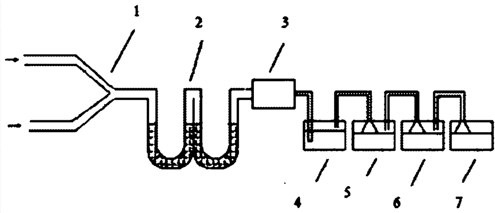
[0019] figure 2 It is a structural schematic diagram of the equipment for catalytic hydrolysis of Freon in the present invention. like figure 2 As shown, according to the running direction of Freon and water vapor, the equipment includes a tee pipe 1, a U-shaped reactor 2, a heat exchanger 3, and an absorption device (the absorption device is four absorption towers, i.e. absorption towers 4, 5, 6, 7), the tee pipe is connected with the U-shaped reactor, and the U-shaped reactor has two sections, the first section is connected with the tee pipe, the second section is connected with the heat exchanger, and the outlet end of the second section of the U-shaped reactor is connected with the heat exchanger. The exchanger is connected, and the outlet of the heat exchanger is connected with the absorption device. The device has simple structure, low cost and high decomposition and absorption efficiency.
Embodiment 3
[0021] use figure 2 As shown in the equipment for catalytic hydrolysis of freon, water vapor and freon are respectively passed into the tee pipe 1 from both ends, and then pass through the U-shaped reactor 2. The U-shaped reactor is divided into two sections, which are filled with aluminum sulfate, aluminum phosphate, phosphoric acid Iron mixture (aluminum sulfate, aluminum phosphate, iron phosphate are dried and dehydrated, passed through a 100-mesh sieve, and then mixed according to a molar ratio of 1:0.3:0.3), the mixed gas passes through the U-shaped reactor, and then exchanged by the heat exchanger 3 After cooling, it enters the absorption device (absorption towers 4, 5, 6, and 7 form the absorption device of this scheme). The temperature of the U-shaped reactor in the first section is controlled at 400°C, and the temperature in the second section is controlled at 510°C. At the same time, the flow rate of the Freon airflow and water vapor is controlled to make the Freon ...
PUM
 Abstract
Description
Claims
Application Information
 - Generate Ideas
- Intellectual Property
- Life Sciences
- Materials
- Tech Scout
- Unparalleled Data Quality
- Higher Quality Content
- 60% Fewer Hallucinations
Browse by: Latest US Patents, China's latest patents, Technical Efficacy Thesaurus, Application Domain, Technology Topic, Popular Technical Reports.
© 2025 PatSnap. All rights reserved.Legal|Privacy policy|Modern Slavery Act Transparency Statement|Sitemap|About US| Contact US: help@patsnap.com