Satellite time synchronization based electric power line fault location system and method

A technology of time synchronization and power lines, applied in the direction of fault location, information technology support system, etc., can solve problems such as difficult overhead line application, large fault location deviation, and no problem of zero-sequence current collection of overhead lines, so as to reduce data The effect of traffic flow, efficiency improvement, data transmission efficiency improvement and line fault judgment and location efficiency

Inactive Publication Date: 2013-02-13
王金泽
View PDF5 Cites 40 Cited by
  • Summary
  • Abstract
  • Description
  • Claims
  • Application Information

AI Technical Summary

Problems solved by technology

[0002] At present, the fault location and distance measurement methods of power transmission lines mainly include impedance detection method, reactance detection method and traveling wave distance measurement method. The problem with the above methods is that the fault location deviation is relatively large
The problem existing in this invention is: all the data distributed in different points of the line with time labels are sent back to the main station for fault calculation and analysis, which will inevitably cause problems for the

Method used


Image

  • Satellite time synchronization based electric power line fault location system and method
  • Satellite time synchronization based electric power line fault location system and method
  • Satellite time synchronization based electric power line fault location system and method

Examples


Embodiment Construction

[0032] The present invention will be further described below in conjunction with the accompanying drawings and specific embodiments.

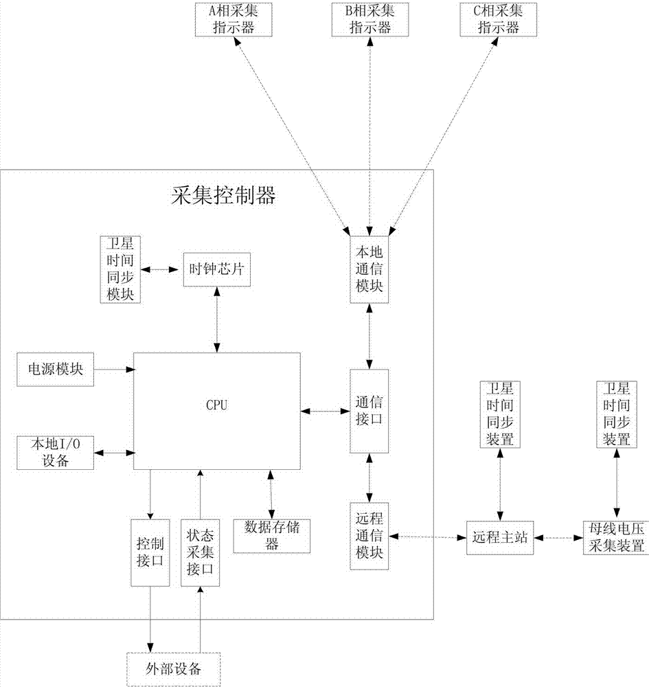
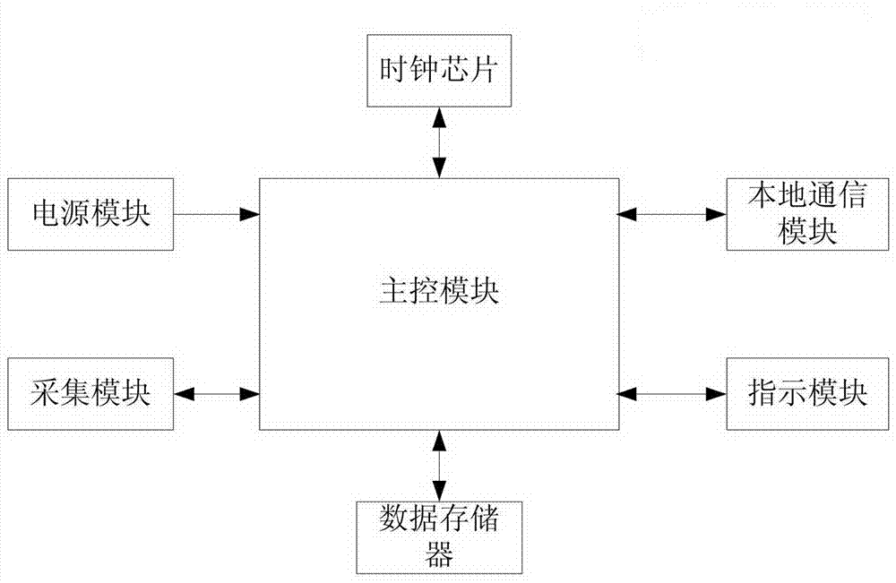
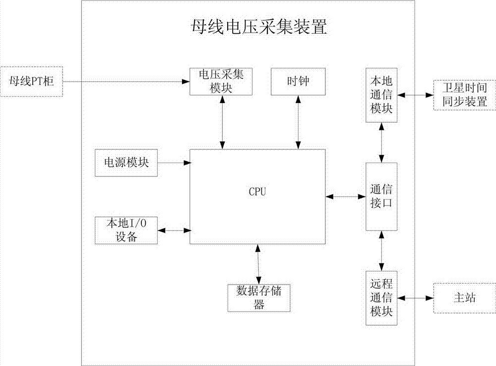
[0033] figure 1 , figure 2 , image 3A power line fault location system based on satellite time synchronization is shown, including an acquisition indicator, an acquisition controller, and a master station. The acquisition indicator includes an acquisition module, a power supply module, a main control module, a local communication module, an indication Module, storage module, acquisition controller includes power supply module, CPU, local I / O equipment, data memory, communication interface, local communication module, remote communication module, described acquisition indicator module also includes the clock chip with temperature compensation , to ensure that the punctual accuracy of the collection indicator can meet the requirements of data synchronous collection when the time synchronization signal sent by the collection controller cannot ...


PUM


Abstract

The invention relates to a satellite time synchronization based electric power line fault location system and a method and belongs to the technical field of smart power grid distribution automation. The system comprises a collecting indicator, collecting controllers, a master station and bus voltage collecting devices, the collecting indicator, the collecting controllers and the bus voltage collecting device are all provided with temperature compensation clock chips, and the master station and the collecting devices of the master station are provided with respective satellite time synchronization modules or satellite time synchronization devices to guarantee that data collected by parts of the system contain accurate time information. By means of a method that the collecting indicator synchronically collects three-phase current of a line and transmits the three-phase current to the collecting controllers by means of wireless communication for math composition of line zero-sequence current, the technical problem of collection of the line zero-sequence current is solved; by means of a distribution and centralization combined line single phase ground fault judgment method which mainly relies on the collecting controllers supplemented by the main station and other devices, data communication flows among the parts of the system are reduced, and data communication between the main station and the collecting controllers is reduced; and by means of a method which combines mobile wireless radio multicast services and point-to-point communication, communication efficiencies and fault location efficiencies of the parts of the system are improved.

Description

technical field [0001] The invention relates to the technical field of smart grid power distribution automation, in particular to a method for locating a power line fault based on satellite time synchronization and a system for realizing the method. Background technique [0002] At present, the fault location and distance measurement methods of power transmission lines mainly include impedance detection method, reactance detection method and traveling wave distance measurement method. The problem of the above methods is that the fault location deviation is relatively large. In my country's distribution network system, the small current grounding system is widely used, that is, the distribution system with the neutral point not grounded or grounded through the arc suppression coil. The distribution network frame is characterized by wide coverage, many branches, complex operating environment, and great influence from external factors. At present, the main method of fault loca...

Claims


Application Information

Patent Timeline
IPC IPC(8): G01R31/08
CPCY04S10/522Y04S10/52
Inventor 王成楷王金泽
Owner 王金泽
Why Eureka
Try Eureka