
Device and method for preparing hard carbide ceramic coating based on composite treatment of large-area high-current pulsed electron beam

A high-current pulse, composite treatment technology, applied in the direction of coating, metal material coating process, ion implantation plating, etc., can solve the problems of coating damage, can not be treated with ceramic coating, etc., to avoid coating oxidation, The effect of high production efficiency

Active Publication Date: 2013-02-20
HARBIN INST OF TECH
View PDF11 Cites 3 Cited by
  • Summary
  • Abstract
  • Description
  • Claims
  • Application Information

AI Technical Summary

Problems solved by technology

[0004] The purpose of the present invention is to deal with the large-area high-current pulsed electron beam technology, which cannot be used for ceramic coating treatment due to the charge accumulation effect caused by arc discharge and damage to the ceramic coating in the past. problems, and proposed a device and method for preparing hard carbide ceramic coatings based on large-area high-current pulsed electron beam composite treatment

Method used


Image

  • Device and method for preparing hard carbide ceramic coating based on composite treatment of large-area high-current pulsed electron beam

Examples


specific Embodiment approach 1

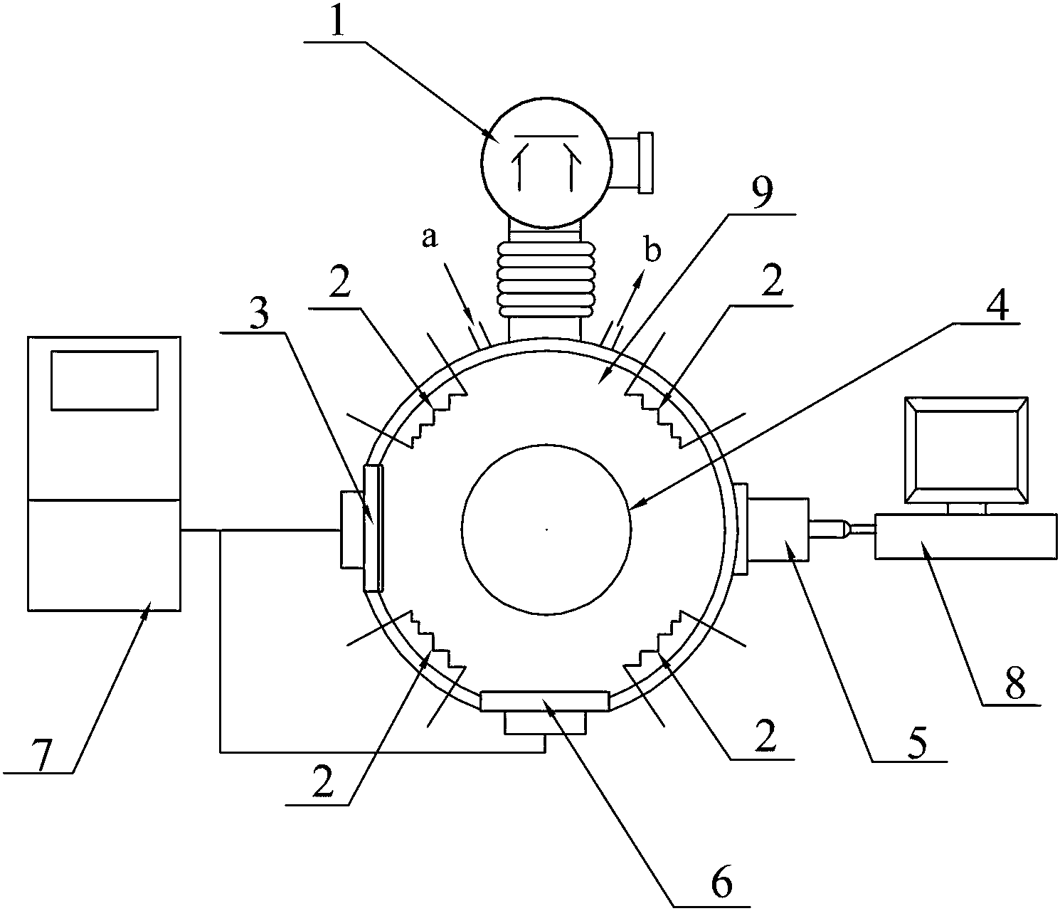
[0024] Specific implementation mode one: the following combination figure 1 Describe this embodiment, the device for preparing hard carbide ceramic coatings based on large-area high-current pulsed electron beam composite treatment described in this embodiment is characterized in that it includes: a vacuum pump group 1, four heaters 2, graphite Target 3, rotating sample stage 4, electron gun 5, metal target 6, coating control power supply 7, computer 8 and vacuum chamber 9;

[0025] The air inlet of the vacuum pump group 1 communicates with the inner chamber of the vacuum chamber 9 through a vacuum tube; The water inlet a and a water outlet b, the water inlet a and the water outlet b communicate with the inner space between the double walls, the water inlet a is used to inject cold water into the middle of the double wall of the vacuum chamber 9, and the water outlet b is used for To discharge the water, cool the temperature in the vacuum chamber 9; a rotating sample stage 4 i...

specific Embodiment approach 2

[0031] Specific implementation mode two: the following combination figure 1 Describe this embodiment. This embodiment is a further description of Embodiment 1. The four heaters 2 described in this embodiment are respectively located in the middle of the vacuum pump group 1 and the graphite target 3, in the middle of the graphite target 3 and the metal target 6, The middle of the metal target 6 and the electron gun 5, the middle of the electron gun 5 and the vacuum pump group 1.

specific Embodiment approach 3

[0032] Specific implementation mode three: the following combination figure 1 This embodiment is described. This embodiment is a further description of Embodiment 1. The water inlet a and the water outlet b described in this embodiment are respectively arranged on both sides of the vacuum tube.


PUM

PropertyMeasurementUnit
Thicknessaaaaaaaaaa
Thicknessaaaaaaaaaa

Abstract

The invention provides a device and a method for preparing a hard carbide ceramic coating based on composite treatment of a large-area high-current pulsed electron beam, and relates to a device and a method for preparing the hard carbide ceramic coating, solving the problem that the conventional large-area high-current pulsed electron beam technology can not be used for ceramic coating treatment because the coating is subjected to arc discharge to be damaged due to charge accumulation effect when performing electronic beam irradiation treatment on the ceramic coating. The device is characterized in that a vacuum pump set is connected with a vacuum chamber; a rotary sample platform is placed in the vacuum chamber; a metal target is placed at one side opposite to the vacuum pump set; a graphite target and an electronic gun are correspondingly arranged; and four heaters are uniformly distributed on an inner wall of the vacuum chamber. The method comprises the following steps: placing a pre-processed component to be processed on the rotary sample platform to be opposite to the graphite target and the metal target; coating N layers of films, and then irradiating by the electronic gun; and heating by the heater to execute returns processing; and then maintaining the temperature and cooling, thus accomplishing the preparation. The device and method are applicable to the field of material surface treatment.

Description

technical field [0001] The invention relates to a device for preparing a hard carbide ceramic coating and a preparation method thereof. Background technique [0002] Large-area high-current pulsed electron beam is an emerging material surface modification technology. Its principle is to generate a beam of pulsed electron beam with extremely high energy density through an electron gun to bombard the surface of the material, so that the surface of the material undergoes instant melting and rapid solidification, and the surface is obtained. Fine-grain structure or non-equilibrium metastable phase can realize the change of material surface properties. At the same time, it can also be combined with vacuum coating technology to achieve material surface alloying. Since the substrate and the alloy coating melt simultaneously during the alloying process, the metallurgical bond between the alloyed layer and the substrate is formed, which completely solves the problem of the bonding f...

Claims


Application Information

Patent Timeline
IPC IPC(8): C23C14/06C23C14/22C23C14/58
Inventor 唐光泽马欣新牛仕超彭冉
Owner HARBIN INST OF TECH
Learn More