
Adjustable compound eye structure optical receiver with visible light wireless communication large view field

An optical receiver and wireless communication technology, applied in the directions of optics, optical components, optical waveguides and light guides, etc., can solve the problems of light loss, difficulties in the processing of crystal cones, and inability to adjust the direction.

Inactive Publication Date: 2013-02-20
JIANGSU UNIV
View PDF7 Cites 18 Cited by
  • Summary
  • Abstract
  • Description
  • Claims
  • Application Information

AI Technical Summary

Problems solved by technology

However, when the external light in these two structures enters the lens, it needs to be gathered layer by layer. Part of the focused light in the previous layer will pass through the gap of the single lens in the next layer, and this part of the light will be lost.
And the direction cannot be adjusted. At the same time, there are difficulties in the processing of crystal cones.

Method used


Image

  • Adjustable compound eye structure optical receiver with visible light wireless communication large view field
  • Adjustable compound eye structure optical receiver with visible light wireless communication large view field
  • Adjustable compound eye structure optical receiver with visible light wireless communication large view field

Examples


Embodiment Construction

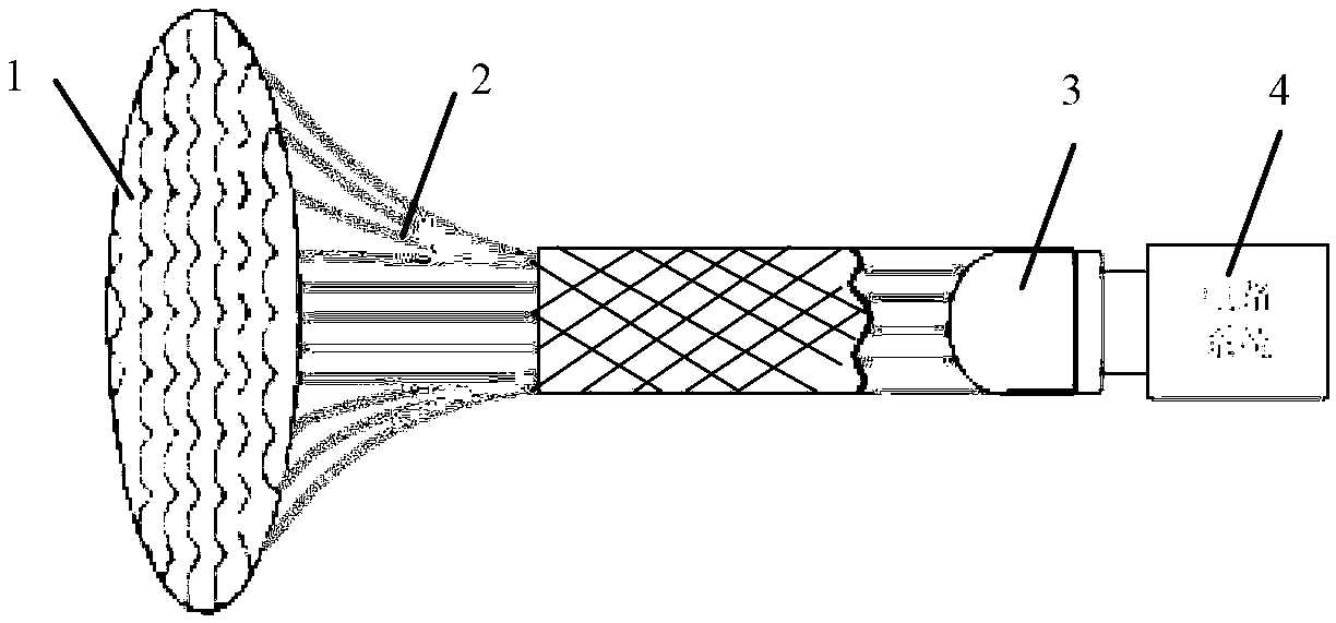
[0031] figure 1 It is a block diagram of the compound eye structure optical receiving system. It consists of fly-eye lens, optical fiber (bundle), photodetector and circuit system connected in sequence. The specific implementation is carried out according to this system block diagram. figure 2 The optical receiving end system shown is mainly composed of fly-eye lens 1 , plastic optical fiber 2 , photodetector 3 and circuit system 4 . The diameter of the fly eye lens is 1.43cm, the diameter of the plastic optical fiber is 1mm, and the numerical aperture NA is 0.5. One end of the plastic optical fiber is combined with a matching microlens, and the other end is fixed by the sleeve and concentrated on the end of the photodetector placed in the sleeve. The electrical signal converted by the photodetector enters the circuit system to be processed in the next step. In addition, since the base of the compound eye is a movable structure, the length of the plastic optical fiber sh...


PUM


Abstract

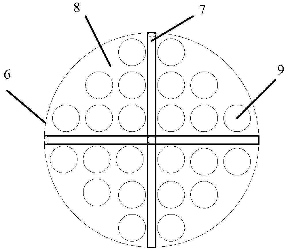
The invention provides an adjustable compound eye structure optical receiver with a visible light wireless communication large view field, which is formed by a compound eye lens, optical fibers, a photoelectric detector and a circuit system, which are connected in sequence, wherein the compound eye lens is formed by a micro-lens array and a base; the base is formed by four equal organic glass flat plates and a cross-shaped connecting shaft; the cross-shaped connecting shaft and the organic glass flat plates are connected to form a circular base in a rotating manner; a circular rolling bead is embedded into a central crossed part of the cross-shaped connecting shaft; the four organic glass flat plates can rotate around the cross-shaped connecting shaft in the horizontal direction or the vertical direction; the base is provided with a plurality of through holes and lenses embedded into the through holes; the first surface of each micro lens is a convex surface and the second surface of each micro lens is a plane and is connected with the end surface of the optical fiber; and the diameter of each micro-lens is slightly larger than that of the optical fiber. The adjustable compound eye structure optical receiver with the visible light wireless communication large view field has a large receiving view field and a high light transmission rate.

Description

technical field [0001] The invention relates to the field of optoelectronics, in particular to the optical fiber coupling and transmission problems at the receiving end of visible light communication. Background technique [0002] With the development of visible light wireless communication systems, higher requirements are placed on the performance of receivers. The receiving end needs to have the characteristics of miniaturization, large field of view, high signal-to-noise ratio, and light weight. Due to the receiving area of ​​the photodetector, the field of view is very small, which is not conducive to the collection of optical information. Therefore, it is hoped that the optical system function of the front end of the receiver is similar to the antenna function in wireless communication: large field of view, large gain effect. However, in the existing optical lens used as an optical system for optical information collection, the lens is a non-movable single-aperture st...

Claims


Application Information

Patent Timeline
IPC IPC(8): G02B6/42G02B3/00G02B6/02
Inventor 朱娜吴俊峰江晓明
Owner JIANGSU UNIV
Learn More