
Coating technique of LED fluorescent powder

A coating process and phosphor technology, applied in the directions of coating, electrolytic coating, electrophoretic plating, etc., can solve the problem of direct coating of phosphors, and achieve the effect of good consistency, strong controllability and uniform light

Active Publication Date: 2015-01-21
厦门多彩光电子科技有限公司
View PDF5 Cites 0 Cited by
  • Summary
  • Abstract
  • Description
  • Claims
  • Application Information

AI Technical Summary

Problems solved by technology

[0014] The technical problem to be solved by the present invention is to provide a LED phosphor coating process, which solves the problem caused by the direct coating of phosphor powder on the LED chip by separating the phosphor powder from the LED chip; High-resistance phosphor layer, solving the deficiencies of the electrophoresis method in the prior art

Method used


Image

  • Coating technique of LED fluorescent powder
  • Coating technique of LED fluorescent powder
  • Coating technique of LED fluorescent powder

Examples


Embodiment Construction

[0038] The present invention will be further described in conjunction with the accompanying drawings and specific embodiments.

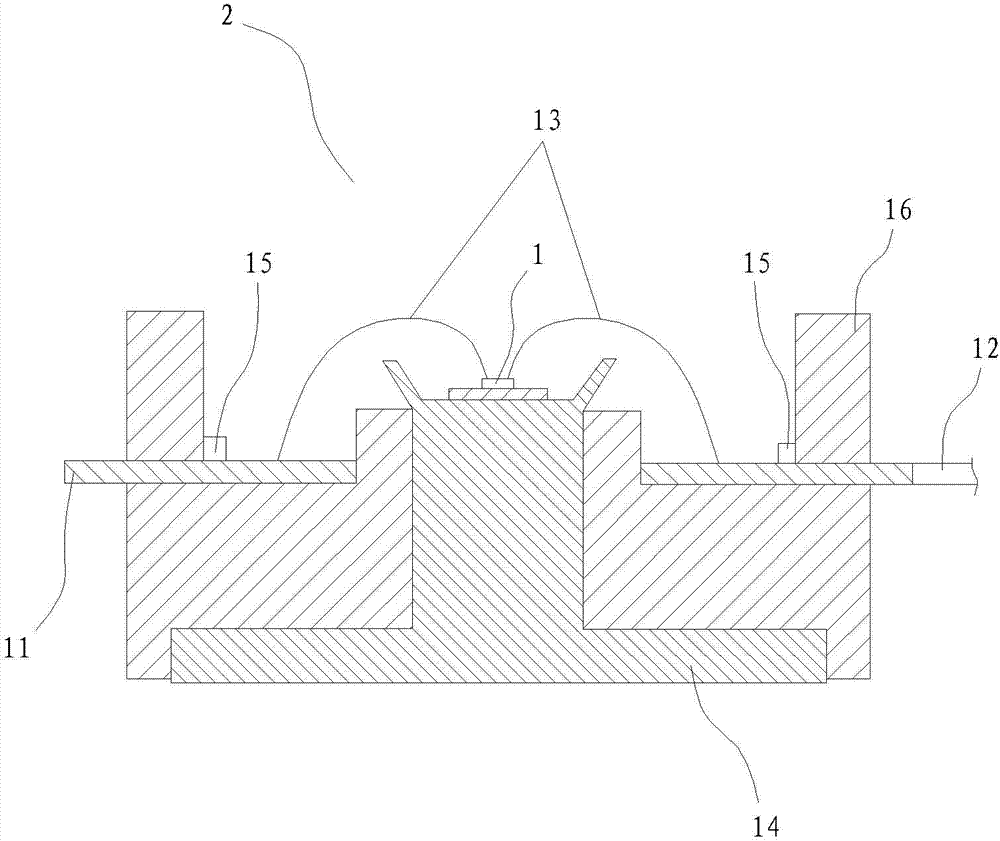
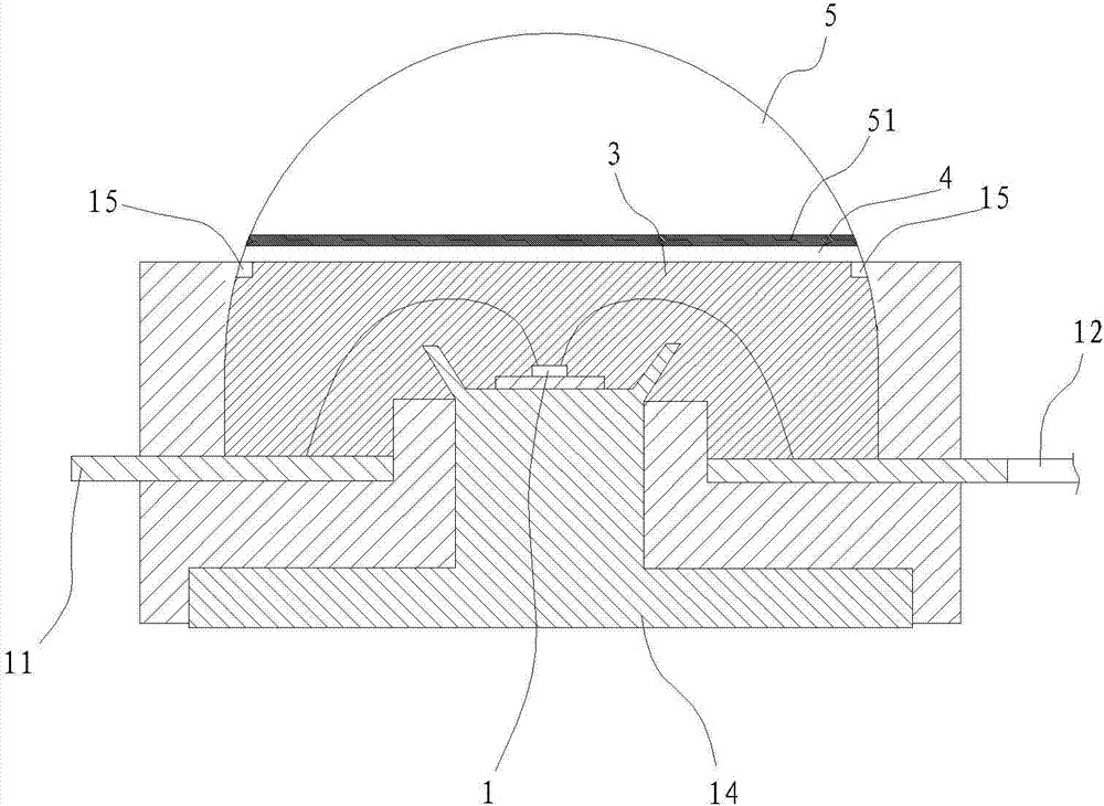
[0039] The high-power LED bracket is now taken as a specific example to illustrate the LED phosphor coating process of the present invention. Such as figure 1 with figure 2 As shown, the LED packaging structure includes an LED chip 1 , a bracket 2 , a silica gel layer 3 , a phosphor layer 4 , and an optical lens 5 . The non-light-emitting surface of the optical lens 5 is provided with an ITO (Indium Tin Oxides, nanometer indium tin metal oxide) conductive layer 51 , and the outer surface of the optical lens 5 is in the shape of a free-form surface and has no conductive function.

[0040] The bracket 2 is provided with a cup and bowl for placing the LED chip 1, a positive conductive pin 11 and a negative conductive pin 12 leading out the positive and negative poles of the LED chip 1 through a wire 13, and a cover covering the positive conductive pi...


PUM

PropertyMeasurementUnit
concentrationaaaaaaaaaa

Abstract

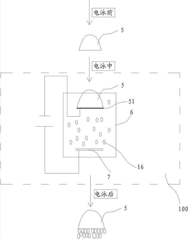
The invention relates to a coating technique of LED fluorescent powder. The coating technique of the LED fluorescent powder comprises the following steps of: 1, producing an optical lens, wherein a non-light emitting surface of the optical lens is equipped with an ITO (Indium Tin Oxide) conducting layer, the outer surface of the optical lens is shaped in a free curved surface, and a lens layer has no conducting function; 2, preparing a fluorescent powder layer by the electrophoretic deposition method, and coating the fluorescent powder layer on the ITO conducting layer of optical glass; and 3, placing the optical lens produced in the step 2 in an oven for baking to remove water and volatilize organic matters. The coating technique of the LED fluorescent powder disclosed by the invention is applied in the production of the LED fluorescent powder layers.

Description

technical field [0001] The present invention relates to LEDs (Light-Emitting Diodes, light-emitting diodes), in particular to an LED packaging structure excited by far-field. Background technique [0002] There are many ways to achieve white light from LEDs, such as RGB chip combination, blue chip to excite phosphor, UV chip to excite phosphor, etc. Currently, the most commonly used method is to coat phosphor on blue or near-ultraviolet LED chips. White light reflection. Using the blue light (420nm-470nm) or near-ultraviolet light (370nm-410nm) emitted by the LED chip as the main spectrum, the phosphor absorbs the main spectrum and is excited to generate a sub-spectrum longer than the main spectrum wavelength, thereby converting to dual wavelength or Three-wavelength white light. In the above process, the packaging structure and process technology of fluorescent materials (phosphor powder) covering LEDs are the key technologies for white LEDs. [0003] Phosphor powder is ...

Claims


Application Information

Patent Timeline
Patent Type & Authority Patents(China)
IPC IPC(8): H01L33/50B05D5/06C25D13/12
CPCH01L2224/48091H01L2924/181
Inventor 苏水源
Owner 厦门多彩光电子科技有限公司
Learn More