

Continuous spinning system of poly (p-phenylene terephthalamide)
A technology of poly-p-phenylene terephthalamide and spinning system, which is applied in the direction of spinning solution preparation, filament forming treatment, textile and papermaking, etc. Solving problems such as long time consumption, to achieve the effect of improving production efficiency and finished silk quality, easy reproduction of large-scale industrialization, and easy and smooth material advancement
- Summary
- Abstract
- Description
- Claims
- Application Information
AI Technical Summary
Problems solved by technology
Method used
Image

Examples
Embodiment 1
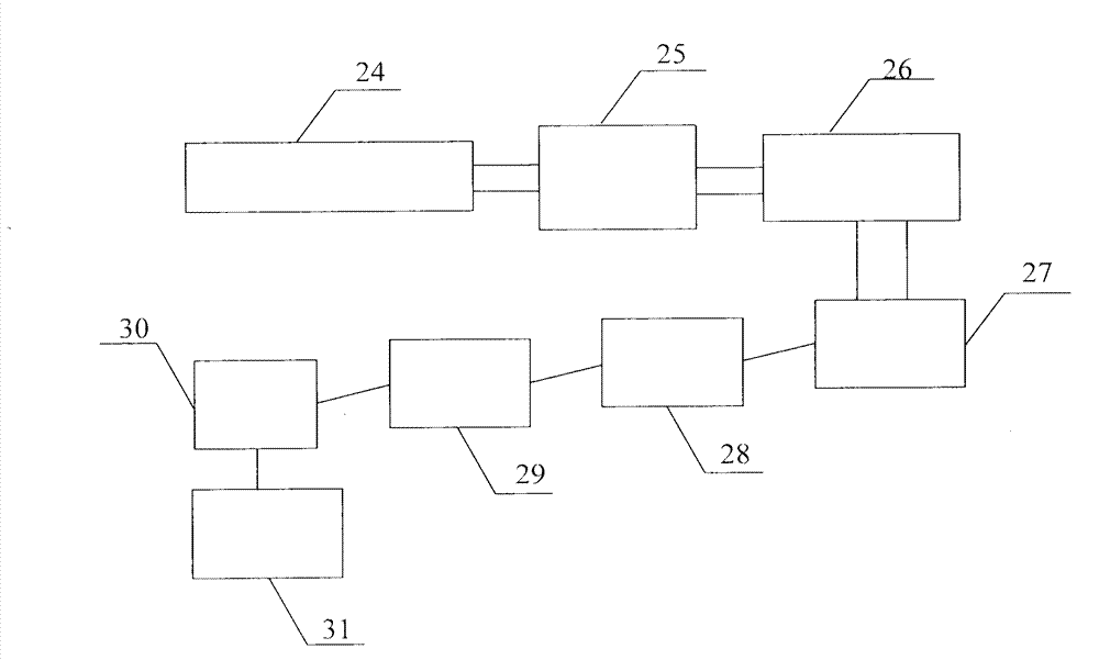
[0054] Such as figure 1 Shown, a kind of continuous spinning system of poly-p-phenylene terephthalamide, it has spinning dope screw mixing and dissolving machine 24, filter 25, spinning machine 26; The material output port connects the material input port of filter 25, and the material output port of filter machine 25 connects the material input port of spinning machine 26; After being washed with water, it is dried by the dryer 29, oiled by the oiler 30, and wound by the winder 31 to form the final product.
[0055] In the system device, the structure of the spinning dope screw mixing and dissolving machine 24 is as follows: Figure 5-11 shown;
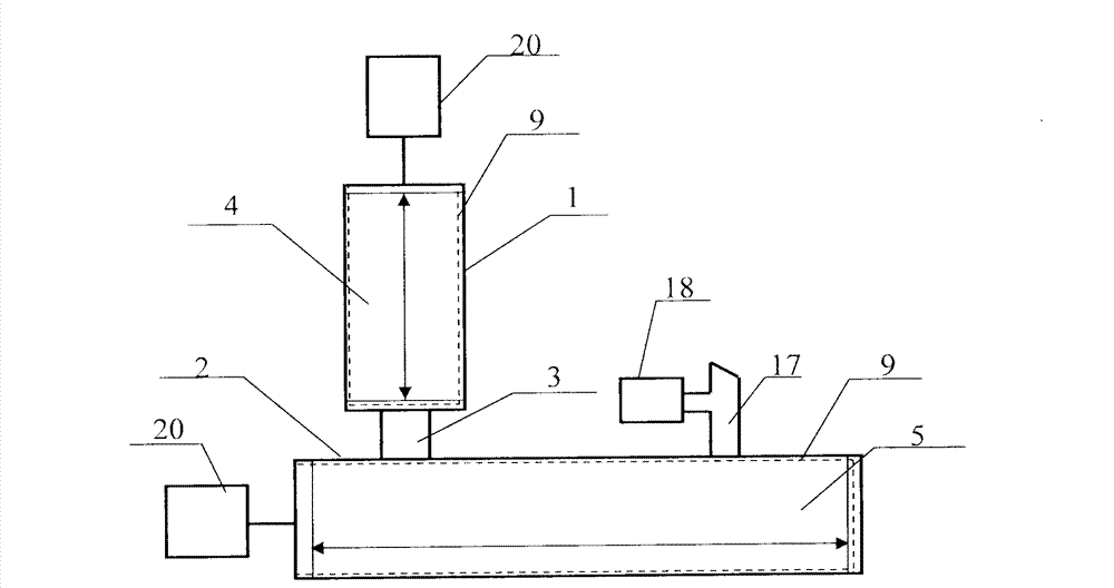
[0056] Such as figure 2 As shown, it has a premixing screw extruder 1 and a miscible screw extruder 2; the two ends of the connecting piece 3 are respectively sealed with the premixing screw extruder 1 and the miscible screw extruder 2 to ensure that the material flows from the The pre-mixing screw extruder 1 enters the miscible...
Embodiment 2
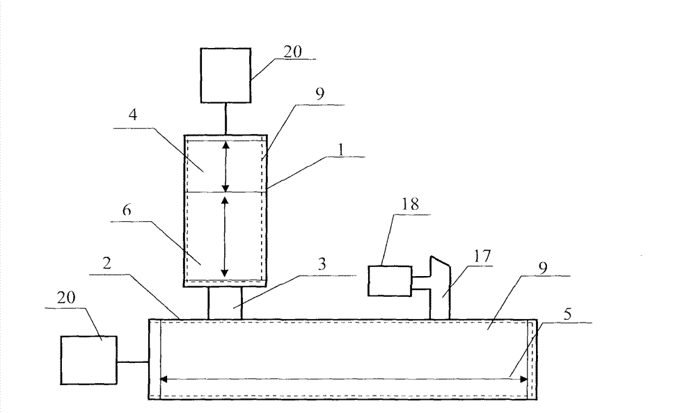
[0076] A continuous spinning system of poly-p-phenylene terephthalamide, its structure is basically the same as that of embodiment 1, the difference is only on the spinning dope screw mixing and dissolving machine 24, such as image 3 As shown, there is also a mixing section 6 in addition to the feeding section 4 on the pre-mixing screw extruder 1, and the screw 9 of the feeding section 4 and the mixing section 6 can have different forms, so that the feeding section 4 can quickly use the spinning stock solution It is fed into the pre-mixing screw extruder, and the mixing section 6 can realize the efficient mixing of the spinning dope; according to the different functions of the feeding section 4 and the mixing section 6, the length ratio between the two can be 1:1~1 : 30; The miscible screw extruder 2 has only the miscible section 5, and the exhaust chamber 17 is opened on the miscible section 5.
[0077] The mixing section 6 disperses and mixes the PPTA powder and sulfuric acid...
Embodiment 3
[0079] A continuous spinning system of poly-p-phenylene terephthalamide, its structure is basically the same as that of embodiment 1, the difference is only on the spinning dope screw mixing and dissolving machine 24, such as Figure 4 As shown, the pre-mixing screw extruder 1 has a feeding section 4 and a mixing section 6 , and the miscible screw extruder 2 only has a degassing section 7 and a pressure regulating section 8 .
[0080] The pressure regulating section 9 regulates the pressure of the spinning dope coming from the previous section, so that the pressure of the material at the screw outlet can better meet the process requirements, and can adjust the pressure of the spinning dope when it enters the spinning process to ensure the aramid filaments are ejected Uniformity; realized by single thread block 15 or double thread block 14 etc. alone or in combination;
PUM
 Abstract
Description
Claims
Application Information