Phase noise compensative amplification system

A phase noise compensation and amplification system technology, applied in the direction of phonon exciters, laser components, electrical components, etc., can solve the problems affecting the amplification effect of the amplifier, reducing the pump energy utilization efficiency of the amplification system, and reducing the system’s responsibility. Accuracy, improvement of time-frequency domain control accuracy, and the effect of slowly changing drift

Inactive Publication Date: 2013-03-06
广东华快光子科技有限公司
View PDF2 Cites 7 Cited by
  • Summary
  • Abstract
  • Description
  • Claims
  • Application Information

AI Technical Summary

Problems solved by technology

Moreover, the spontaneous emission effect in the amplification process not only reduces the utilization efficiency of the pump energy by the amplification system, but also introduces additional phase noise and parasitic spectral components to the pulse, which seriously affects the amplification effect of the amplifier.

Method used


Image

  • Phase noise compensative amplification system
  • Phase noise compensative amplification system
  • Phase noise compensative amplification system

Examples


Embodiment 1

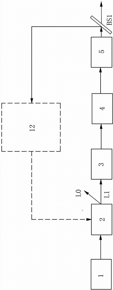
[0038] Such as figure 2 As shown, a nonlinear polarization rotation mode-locked femtosecond laser is used as a seed source, and the phase noise is precompensated to realize a high-power fiber optic comb.

[0039] Its implementation details:

[0040] (1) A nonlinear polarization-rotating ytterbium-doped fiber laser is selected as the ultrashort pulse oscillation source, which is characterized in that the pulse repetition frequency fr is precisely locked.

[0041] (2) The output light of the oscillator 1 passes through an acousto-optic frequency shifter 2, whose driving frequency is fd, and its first-order (diffraction) light L1 produces a frequency shift of -fd, and is used as output light.

[0042] (3) Use single-mode fiber as the chirped pulse stretcher 3 to widen the time-domain width of the seed laser to avoid damage to optical devices caused by ultra-high peak power and pulse distortion caused by nonlinear effects during ultra-short pulse amplification.

[0043] (4) Use...

example 2

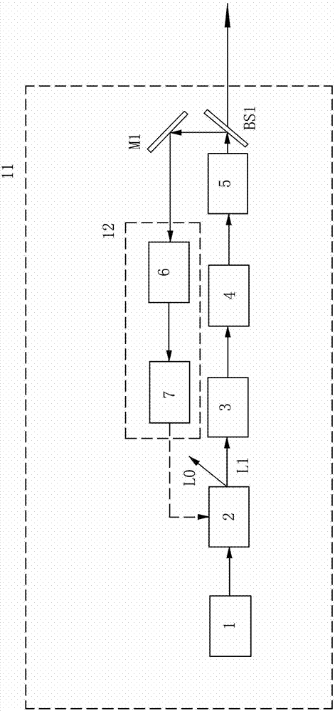
[0053] The optical comb is used as the seed source, and the phase noise pre-compensation technology is used to realize the precise control of the zero-frequency slow-variation drift during the pulse amplification process of the femtosecond optical comb. The specific scheme is shown in the figure.

[0054] Such as image 3 Shown:

[0055] (1) Oscillator 1 is an optical comb light source, characterized in that:

[0056] (a) Laser repetition frequency fr is precisely locked, and the locking accuracy is <1mHz;

[0057] (b) The carrier envelope phase frequency f0 of the pulse is precisely locked with a locking accuracy of <10mHz.

[0058] (2) The seed light of the optical comb passes through the acousto-optic frequency shifter (AOFS) 2, and its first-order diffracted light is sent to the stretcher 3, and then it is amplified with high power by the chirped pulse cascade amplifier 4, and then compressed by the compressor 5 The high-power amplified pulse is compressed to the femtos...

example 3

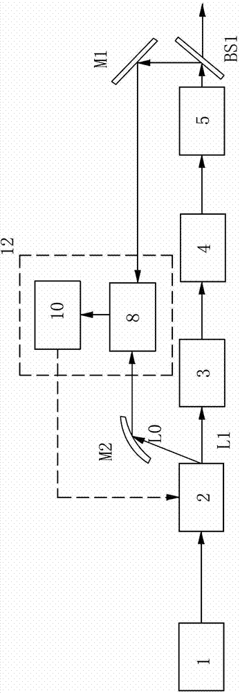
[0065] Cascaded noise compensated amplification. This example is based on examples 1 and 2, using the output light of example 1 as the seed light source of example 2, and using the structure of example 2 to further amplify the output pulse of example 1 with high power. The specific scheme is shown in the figure.

[0066] Such as Figure 4 Shown:

[0067] (1) The seed light source 11 adopts the structure of Embodiment 1, wherein the oscillator is an ordinary mode-locked laser, which is characterized in that the pulse repetition frequency is precisely locked, and the locking accuracy is <1 mHz.

[0068] (2) The seed light enters the low-noise power amplification system in Embodiment 2 after passing through a pair of ramp systems 9 . Wherein, part of the signal amplified by the second filter amplifier 10 - 1 of the second beat frequency system 8 - 1 is used to drive the second acousto-optic frequency shifter 2 - 1 , and the other part is used to control the relative distance o...


PUM


Abstract

The invention discloses a phase noise compensative amplification system, and the phase noise compensative amplification system comprises an oscillator (1) for outputting a seed light source, and the phase noise compensative amplification system is characterized in that the output end of the oscillator (1) is provided with an acoustic-optic frequency shifter (2) for outputting zero-order light (LO) and first-order light (L1) after processing the seed light source, wherein the output end of the first-order light (L1) of the acoustic-optic frequency shifter (2) is provided with a stretcher (3), the output end of the stretcher (3) is provided with a cascade amplifier (4), the output end of the cascade amplifier (4) is provided with a compressor (5), the output end of the compressor (5) is provided with a number one beam splitting sheet (BS1), the reflection light of the number one beam splitting sheet (BS1) is communicated with a compensative amplification system (12), and the compensative amplification system (12) is connected with the acoustic-optic frequency shifter (2) and supplies a control signal to the acoustic-optic frequency shifter (2).

Description

【Technical field】 [0001] The invention belongs to the technical field of ultrafast strong field laser, in particular to a noise reduction amplification system. 【Background technique】 [0002] High-power fiber optic combs have a wide range of applications in the fields of high-order harmonic generation, precision spectral measurement, and micro-nanoscale material processing. With the development of double-clad fiber manufacturing technology and high-brightness semiconductor laser pumping technology, the average output power of pulsed laser has reached nearly kilowatts, which has promoted the development of high-power fiber optic frequency combs. At present, there are two main methods to realize the phase stabilization of high-power fiber optic comb carrier envelope: phase servo phase-locked loop technology and difference frequency generation method. The phase servo phase-locked loop technology is easily limited by the feedback bandwidth. The pump modulation during the feedba...

Claims


Application Information

Patent Timeline
Patent Type & Authority Applications(China)
IPC IPC(8): H01S3/13
Inventor 梁崇智曾和平闫明赵健
Owner 广东华快光子科技有限公司
Why Eureka
Try Eureka