Mixed energy utilization device for integrated rotary radiant boiler preheating boiler

A preheating boiler and hybrid technology, applied in the field of integrated rotary radiant boiler preheating boiler hybrid energy utilization device, can solve the problems of complex reliability, large space occupation, increased equipment investment, etc., and achieve energy recovery and utilization rate High efficiency, convenient transportation and installation, and improved energy efficiency

Active Publication Date: 2013-03-20
DONGFANG ELECTRIC CORP LTD
View PDF7 Cites 4 Cited by
  • Summary
  • Abstract
  • Description
  • Claims
  • Application Information

AI Technical Summary

Problems solved by technology

However, the waste heat boilers in the prior art still have problems such as complex structure and short service life, which are mainly manifested in:
[0005] (1) Shell pulverized coal gasification technology uses 1.3 to 1.5 times the circulating cold air to quench the high-temperature syngas, which increases the size of the convective waste heat boiler and its subsequent syngas dust removal equipment, and increases the investment in equipment, and the syngas circulation compressor increases The energy consumption of the gasification device is reduced; due to the ash accumulation in the convection boiler, the heat transfer effect of the convection boiler is affected, and

Method used


Image

  • Mixed energy utilization device for integrated rotary radiant boiler preheating boiler
  • Mixed energy utilization device for integrated rotary radiant boiler preheating boiler
  • Mixed energy utilization device for integrated rotary radiant boiler preheating boiler

Examples


Example Embodiment

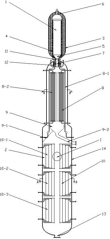
[0029] Such as figure 1 As shown, the integrated rotary radiant boiler preheating boiler hybrid energy utilization device includes a gasification furnace body 1 and a heat recovery device 2. The gasification furnace body 1 is located above the heat recovery device 2 and is controlled by the pressure of the gasification furnace The shell 3, the refractory lining (or water wall) of the gasification furnace 4, the lower slag port 5 and the nozzle channel 6. Take the entrained-bed gasification furnace body with a single-nozzle refractory lining structure as an example.

[0030] In fact, the gasifier is an entrained-bed gasifier, which can be a single nozzle gasifier, or a nozzle gasifier, or a coal slurry or pulverized coal gasifier, or a water wall or refractory lining gas. Various forms of gasification furnaces such as chemical furnaces.

[0031] The heat recovery device 2 is a radiant boiler preheating boiler hybrid heat recovery device, which includes a synthesis gas inlet 7, a ra...


PUM


Abstract

The invention relates to a mixed energy utilization device for an integrated rotary radiant boiler preheating boiler. The device comprises a gasification furnace body and a heat recovery device, wherein the gasification furnace body is arranged above the heat recovery device; the heat recovery device comprises a synthetic gas inlet, a radiation heat exchange component, a slag bath, a convection heat exchange component and a pressure shell; the synthetic gas inlet is positioned on a seal head on the top of the pressure shell; the radiation heat exchange component is positioned on the upper part of the slag bath; the slag bath is positioned on the upper part of convection heat exchange component; the radiation heat exchange component, the slag bath and the convection heat exchange component are positioned in the pressure shell into a whole; a lower slag port of the gasification furnace body is connected with the top of the heat recovery device through a flange; and the lower slag port is communicated with the synthetic gas inlet. The sensible heat of the gasified coarse synthetic gas can be effectively absorbed, and the generated high-pressure steam or medium-pressure steam is used for power generation or preheating other working media, so that the energy utilization rate is greatly improved, and the energy recycling efficiency is high; and moreover, the overall size of a waste heat boiler is effectively reduced, the device is convenient to manufacture, transport and mount, and the dust accumulation problem in the convection heat exchange area can be eliminated.

Description

technical field [0001] The invention relates to an energy utilization device of coal gasification technology, in particular to an integrated rotary radiant boiler preheating boiler hybrid energy utilization device. Background technique [0002] Coal gasification is one of the most important ways to use coal cleanly and efficiently. Gasification raw materials and oxidants are mixed into the gasifier and react quickly. The high-temperature synthesis gas (about 1400°C) produced is cooled and dedusted before being sent to the next Effective use of workshops. [0003] There are two main cooling methods for high-temperature syngas in coal gasification technology, one is the chilling process, and the other is the waste boiler process. The quenching process is that the high-temperature syngas is fully contacted with the quenching water, so that the gas is cooled down and the molten slag is solidified. The chilling process does not recover the sensible heat in the high-temperat...

Claims


Application Information

Patent Timeline
IPC IPC(8): C10J3/48C10J3/84C10J3/86C10J3/80C10J3/74C10J3/72
CPCY02P20/10Y02P20/129
Inventor 曹立勇张媛张春飞张鑫刘正宁郭盼杜奇樊伟李阳李少华雷宇
Owner DONGFANG ELECTRIC CORP LTD
Why Eureka
Try Eureka