Laser profile modification method for reducing modal coupling error of vibratory silicon micro-machined gyroscope

A silicon micro-gyroscope and modal coupling technology, which is applied in laser welding equipment, instruments, measuring devices, etc., can solve the problems that restrict the performance of micro-gyroscopes, and achieve the effect of low processing conditions, simple operation, and simple principle

Active Publication Date: 2013-03-20
NAT UNIV OF DEFENSE TECH
View PDF4 Cites 1 Cited by
  • Summary
  • Abstract
  • Description
  • Claims
  • Application Information

AI Technical Summary

Problems solved by technology

However, the premise of synchronous demodulation is that the reference signal must have the same frequency and phase as the Coriolis force signal, and in the actual working system, it is difficult to ensure that the reference signal and the Coriolis force s...

Method used


Image

  • Laser profile modification method for reducing modal coupling error of vibratory silicon micro-machined gyroscope
  • Laser profile modification method for reducing modal coupling error of vibratory silicon micro-machined gyroscope
  • Laser profile modification method for reducing modal coupling error of vibratory silicon micro-machined gyroscope

Examples


Embodiment Construction

[0024] The present invention will be further described in detail below in conjunction with the accompanying drawings and specific embodiments.

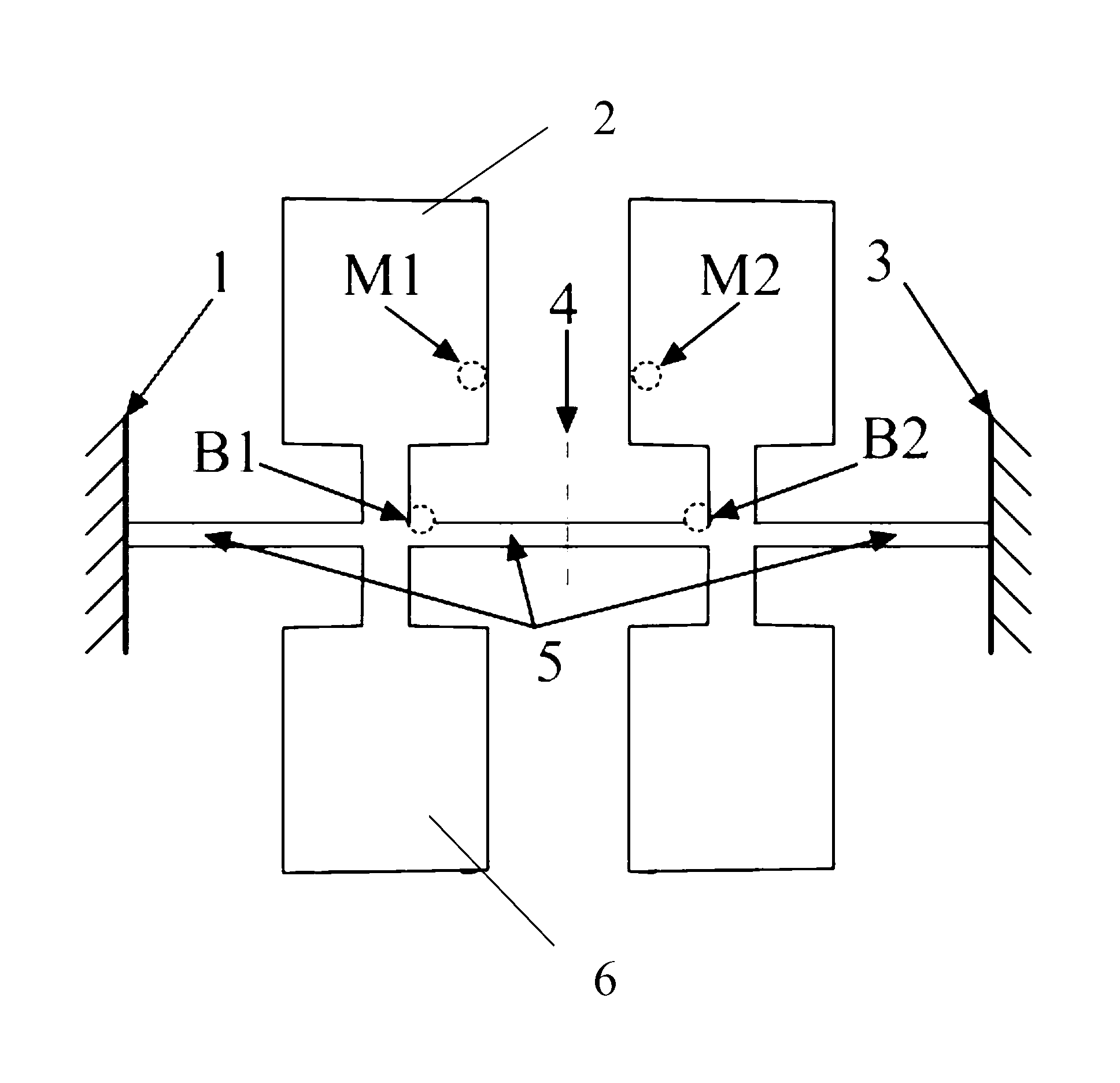
[0025] Such as figure 2 As shown, taking a silicon microgyro chip in a specific application example as an example, the silicon microgyro chip includes a support beam 5 and several mass blocks, and the two ends of the support beam 5 pass through the first anchor point 1 and the second anchor point respectively. 3 fixed, the first mass block 2 and the second mass block 6 form a group and are symmetrically arranged at both ends of the support beam 5 (two pairs of left and right in this example), and they are arranged correspondingly, forming two pairs during work The mass swing centerline 4 between the masses.

[0026] In an ideal situation, there is no processing error in the vibration structure of the silicon micro-gyroscope, and the modal coupling error of the micro-gyroscope is zero at this time. When there are machining errors in...


PUM


Abstract

The invention discloses a laser profile modification method for reducing the modal coupling error of a vibratory silicon micro-machined gyroscope. The method comprises the following steps: 1, signal test: testing the driving signal Vd and the modal coupling error signal Vm of a silicon micro-machined gyroscope chip, and determining the peak values and the phase relationships of the two signals; 2, determining the laser profile modification type according to the signals in step 1; 3, determining the profile modification position according to the signals in the step 1; and 4, carrying out laser profile modification according to the type obtained in step 2 and the position obtained in step 3. The laser profile modification method has the advantages of simple principle, simple operation, reduction of the modal coupling error, and improvement of the working performances of the silicon micro-machined gyroscope.

Description

technical field [0001] The invention mainly relates to the field of processing technology in micro-electro-mechanical systems, in particular to a laser shape modification method for manufacturing silicon micro-mechanical gyroscopes that can reduce modal coupling errors caused by processing errors of silicon micro-gyroscope vibration structures. Background technique [0002] Vibrating silicon micromachined gyroscopes have the advantages of small size, light weight, low cost, high reliability, and easy integration with circuits. They have been widely used in communication equipment, automotive safety and navigation, robotics, aerospace, and game consoles. Vibrating silicon micromechanical gyroscopes are usually made of thin-sheet single-crystal silicon, and are manufactured by semiconductor processing techniques such as wet etching and dry etching, and their structural size can be as small as submicron. [0003] Since the production of the vibrating silicon micromachined gyros...

Claims


Application Information

Patent Timeline
IPC IPC(8): G01C25/00B23K26/36B23K26/42
Inventor 吴学忠肖定邦陈志华贺琨侯占强胡松奇王兴华刘学
Owner NAT UNIV OF DEFENSE TECH
Why Eureka
Try Eureka