Sinter waste-heat utilization process based on purification of sintering flue gas

A technology for sintering flue gas and sintering ore, which is applied in the field of sintering ore waste heat utilization process based on sintering flue gas purification, can solve the problems of "ammonia escape and the continuity of sintering ore waste heat recovery heat source is difficult to ensure, etc., to improve the utilization rate, easy to The effect of simple operation and process flow

Inactive Publication Date: 2013-03-27
武汉钢铁有限公司 +1
View PDF12 Cites 39 Cited by
  • Summary
  • Abstract
  • Description
  • Claims
  • Application Information

AI Technical Summary

Problems solved by technology

[0012] The purpose of the present invention is to solve the above technical problems and provide a very simple process that can not only solve the problem of "ammonia escape" in the process of flue g

Method used


Image

  • Sinter waste-heat utilization process based on purification of sintering flue gas
  • Sinter waste-heat utilization process based on purification of sintering flue gas
  • Sinter waste-heat utilization process based on purification of sintering flue gas

Examples


Embodiment 1

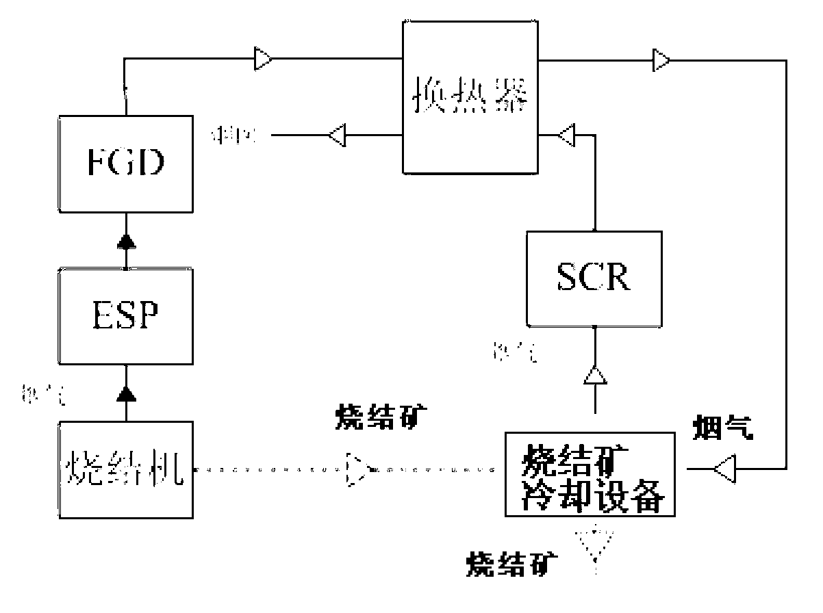
[0036] Example 1 (see figure 1 ):

[0037] The flue gas and sintered ore are drawn out from the sintering machine, and the flue gas is desulfurized at 50-60°C after being subjected to electrostatic precipitator (ESP) and ammonia desulfurization. Indirect heat exchange Pre-heating to 190-230°C, and then direct heat exchange with sintering ore at 800-900°C from the sintering machine in the sinter cooling equipment, after heat exchange, the temperature of desulfurization flue gas above 380°C (tested nitrogen Oxide content higher than 300mg / m 3 ) to obtain purified flue gas after denitrification by SCR method, and the purified flue gas is further exchanged with the above-mentioned desulfurized flue gas in the above-mentioned heat exchanger and cooled to 100-120°C before being discharged. The sintered ore is sent to the next process.

[0038] In this example, after testing, the concentrations of sulfur dioxide and nitrogen oxides in the purified flue gas meet the "Steel Sinterin...

Embodiment 2

[0039] Example 2 (see image 3 ):

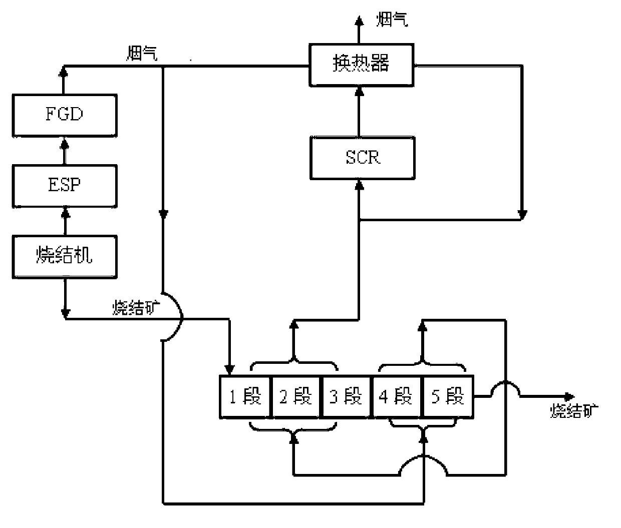
[0040] Wherein, the sinter cooling equipment in this embodiment is an annular cooler, and the annular cooler is divided into 5 sections, see figure 2 , from 1st stage to 5th stage, the sinter temperature gradually decreases, 1st stage, 2nd stage and 3rd stage are high temperature stage, 4-5 stage is low temperature stage.

[0041] The flue gas and sintered ore drawn from the sintering machine are subjected to dust removal (ESP method electric dust removal) and ammonia desulfurization to obtain desulfurized flue gas at 50-60°C. The desulfurized flue gas is divided into two streams, and the first stream is desulfurized The flue gas (accounting for 65-85% by volume of the total desulfurization flue gas) is sent to the low-temperature section (sections 4 and 5) of the annular cooler for a heat exchange with the sinter located in the low-temperature section to raise the temperature, and then sent to the annular cooler. The high-temperature sec...

Embodiment 3

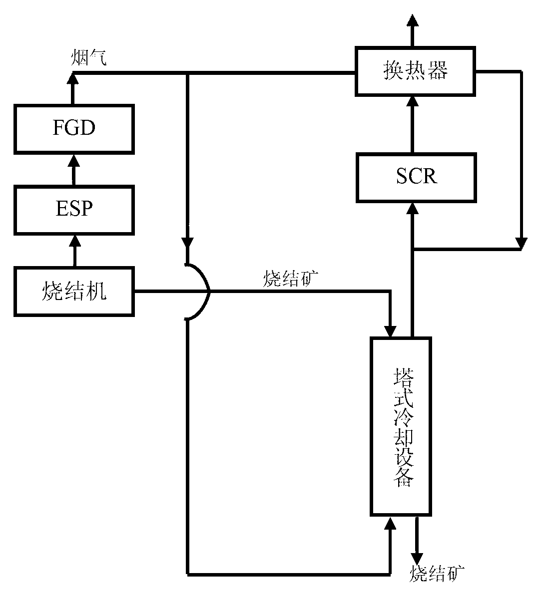
[0043] Embodiment 3 (see image 3 ):

[0044] Among them, the sinter cooling equipment in this embodiment is a tower cooling equipment (such as the "vertical closed tank" disclosed in 200910187381.8)

[0045] The flue gas and sintered ore are drawn out from the sintering machine, and the flue gas is subjected to dust removal (ESP method electric dust removal) and ammonia desulfurization to obtain desulfurized flue gas at 50-60°C. The desulfurized flue gas is divided into two streams, the first desulfurized flue gas Gas (accounting for 65-85% by volume of the total desulfurization flue gas) is sent to the tower cooling equipment to directly exchange heat with the sinter to 430-470°C; The intermediate indirect heat exchange raises the temperature to 190-230°C, and then mixes with the first desulfurization flue gas from the tower cooling equipment to make the flue gas (the nitrogen oxide content is higher than 300mg / m 3 ) when the temperature reaches above 380°C, SCR denitrific...


PUM


Abstract

The invention relates to a sinter waste-heat utilization process based on the purification of a sintering flue gas. The process solves the problems that the sinter waste-heat utilization ratio is low, the operating cost and investment cost on purification of the sintering flue gas are high, and ammonia escape occurs in ammonia process of desulfurization and the like. The technical scheme provided by the invention comprises the steps of obtaining desulfurated flue gas at 50-60 DEG C led by a sintering machine after dust extraction and ammonia process of desulfurization; carrying out direct heat exchange for sintering at 800-900 DEG C led by the sintering machine with the desulfurated flue gas in a sinter cooling device; detecting the desulfurated flue gas which is heated to be higher than 380 DEG C after heat exchange; if the oxynitride content is lower than the emission standard, discharging the desulfurated flue gas as a purified flue gas; if not, discharging the purified flue gas after SCR denitration; and sending the sinter after heat exchange and temperature reduction in the sinter cooling device to the next step. The sinter waste-heat utilization process based on purification of the sintering flue gas provided by the invention is simple in process, low in device investment and operating cost, high in sinter waste-heat utilization ratio and good in purifying effect of sinter flue gas, and ammonia escape is thoroughly solved.

Description

technical field [0001] The invention relates to a method for comprehensive utilization of sinter waste heat and coordinated control of sinter flue gas pollutants, in particular to a sinter waste heat utilization process based on sinter flue gas purification. Background technique [0002] The iron and steel industry is a pillar industry of my country's national economy and a basic industry related to the national economy and the people's livelihood. However, the iron and steel industry is also a high-energy-consumption and high-pollution industry. In 2010, the ton of steel SO 2 The emission is 1.95kg. Sintering flue gas is the main source of SOx and NOx next to power plant flue gas. To reinforce SO 2 Emission reduction. At present, many domestic steel mills have implemented sintering flue gas desulfurization. [0003] Overseas sintering flue gas desulfurization and denitrification technology started earlier, after decades of development, there are many types of desulfuriza...

Claims


Application Information

Patent Timeline
IPC IPC(8): F27D17/00B01D53/75B01D53/60
CPCY02P10/265Y02P10/25
Inventor 吴高明韩军傅连春王剑肖扬汤静芳幸福堂杨秀林
Owner 武汉钢铁有限公司
Why Eureka
Try Eureka